ROW1:
GPIO41 Down Right >> (2) << (2) Clear Select
ROW2:
GPIO42 1 6 8
ROW3:
GPIO43 5 7 # Stop (1)
ROW4:
GPIO44 End << (1) 9 0 3 Play (1)
ROW5:
GPIO45
Shutter
(H)
Shutter
(F) * 2 4
ROW6:
GPIO46 L-Soft R-Soft
Stop (2)/
Gaming
Play (2)/
Gaming Access >> (1)
Row lines are filtered with Z4401 and column lines are filtered with Z4400. Power key is also placed on the
system/RF module. It is connected directly to EM ASIC N2200 PWRONX PIN.
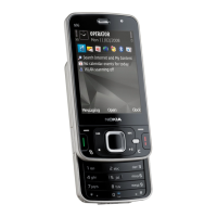
Slide position sensors
Two Hall sensors are used to detect slide movement upwards or downwards. One magnet triggers both
sensors. The magnet is placed in the UI/slide module, under the display. The hall sensor, that detects opening
of the ITU keyboard, is on the bottom side of the PWB. Opening the multimedia keyboard is detected with
the hall sensor that is on the top of the PWB. Hall sensors are connected to the application ASIC (D4800)
GPIO’s.
RM-247
System Module
Page 7 –32 COMPANY CONFIDENTIAL Issue 1
Copyright © 2008 Nokia. All rights reserved.

 Loading...