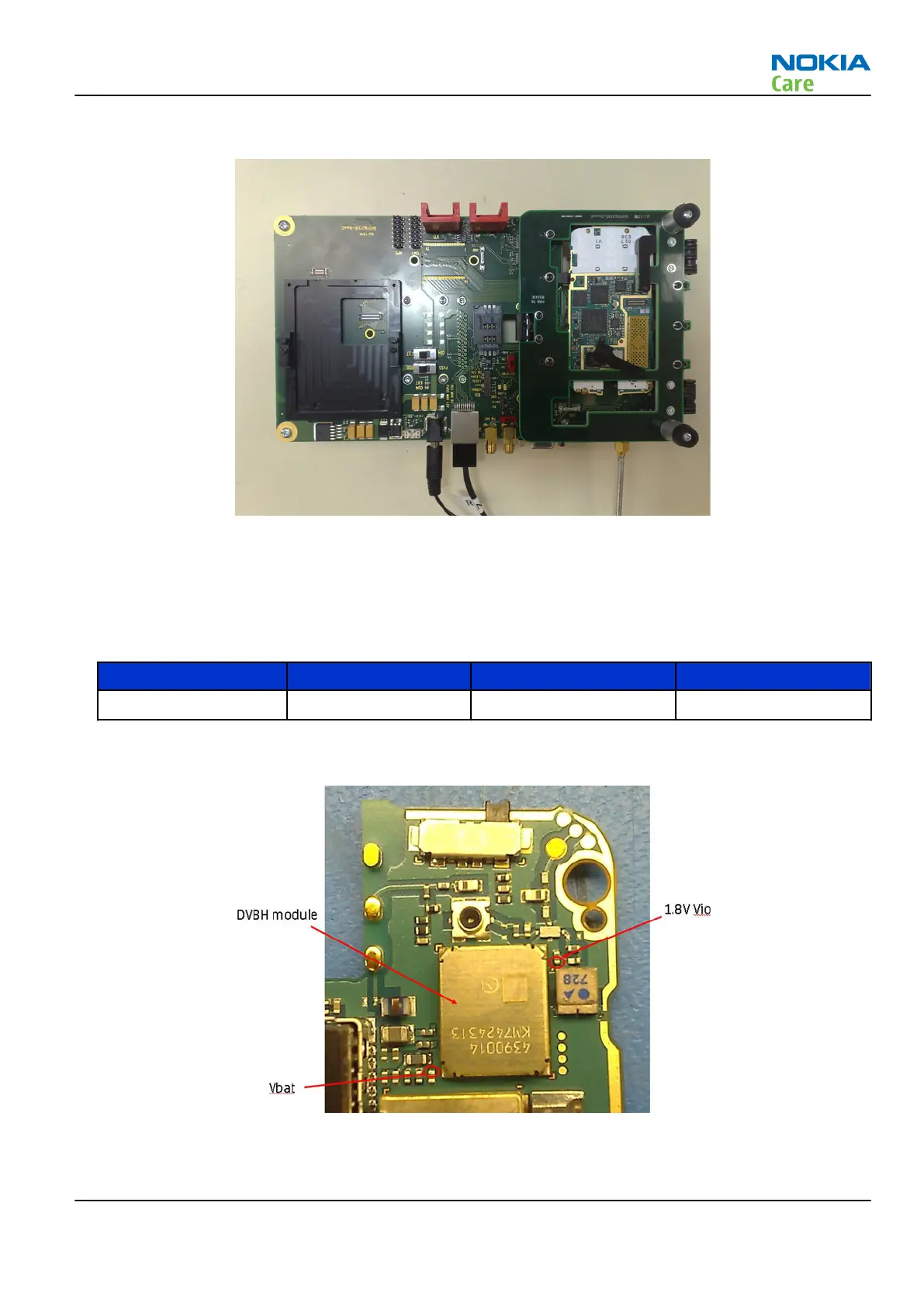
2. Place disassemble phone to module jig.
Figure 41 Phone disassembled and placed to jig
3. Connect cables to the jig.
4. Connect cable from Signal Generator to Module Jig DVB-H SMA connector.
5. Proceed the steps 2-7 according to chapter RM-247 Galvanic DVB-H RF test measurement with FS-51
(page 6–8).
Frequency Signal level RSSI value Tolerance
639 -30 dBm -33 dBm +/-3 dBm
DVB-H engine R5 measurement guide
Figure 42 DVB-H module
RM-247
TV troubleshooting
Issue 1 COMPANY CONFIDENTIAL Page 6 –11
Copyright © 2008 Nokia. All rights reserved.

 Loading...