Installation
1040-0011 Revision 31
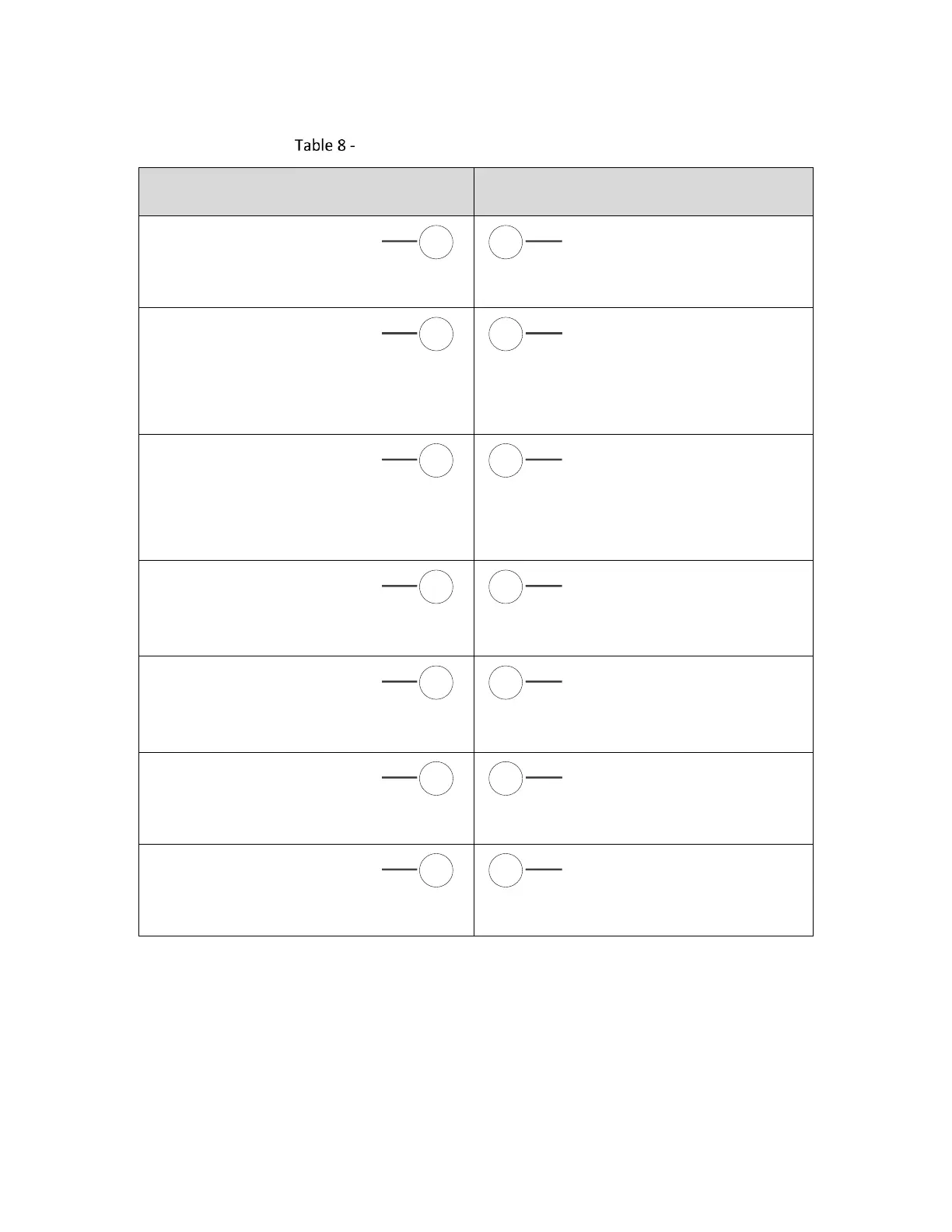
Connector J13 (Auxiliary) Signal Descriptions
Odd-numbered Pins (1 – 63)
Even-numbered Pins (2 – 64)
EXT-VCC5V0
Fused 5 Volts available for logic on
an Auxiliary I/O board
GND
Digital ground reference
AUX_AMOTF1_DP
Secondary mark-on-the-fly encoder
input. Expected to be connected
to an RS-485 positive “A” phase
differential signal or a 5V TTL
signal.
AUX_AMOTF1_DN
Secondary mark-on-the-fly encoder
input. Expected to be connected to
an RS-485 negative “A” phase
differential signal.
AUX_BMOTF1_DP
Secondary mark-on-the-fly encoder
input. Expected to be connected
to an RS-485 positive “B” phase
differential signal or a 5V TTL
signal.
AUX_BMOTF1_DN
Secondary mark-on-the-fly encoder
input. Expected to be connected to
an RS-485 negative “B” phase
differential signal.
AUX_TX1_DP
Differential RS-485 serial transmit
data to smart-stepper motor
controllers - positive
AUX_TX1_DN
Differential RS-485 serial transmit
data to smart-stepper motor
controllers - negative
AUX_RX1_DP
Differential RS-485 serial receive
data from smart-stepper motor
controllers - positive
AUX_RX1_DN
Differential RS-485 serial receive
data from smart-stepper motor
controllers - negative
AUX_STEP0
Step control signal for a
programmable stepper motor
AUX_DIR0
Direction control signal for a
programmable stepper motor
GND
Digital ground reference
GND
Digital ground reference