4-73
4-2 Function Mode
4
Functions
Analog Input
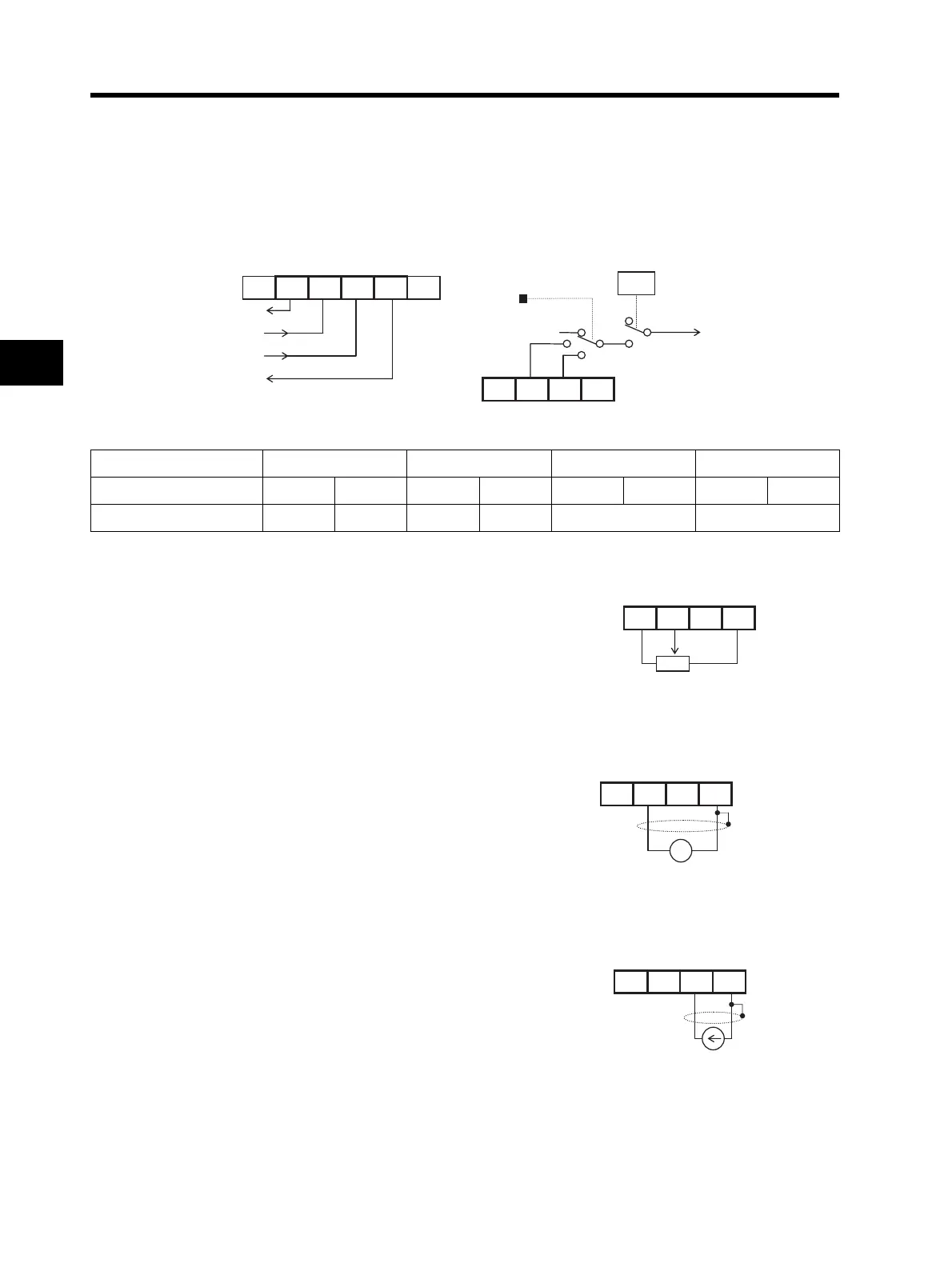
Two types of external analog inputs are available for frequency reference.
For voltage input, you can set a frequency from 0 to maximum by applying a voltage from 0 to 10 V
between inputs FV and FC. For current input, apply 4 to 20 mA between inputs FI and FC. Note that
voltage and current cannot be input simultaneously. Also, do not connect the signal lines for inputs
FV and FI simultaneously.
Using the External Volume (VR)
Inputting the Voltage
Inputting the Current
Reference voltage (10 V)
Voltage input
Current input
nalog ground
FS FV FI FC
[AT]
A001
Inverter VR
Frequency setting
FS FV FI FC
A005 set value02030405
AT terminal input status OFF ON OFF ON OFF ON OFF ON
Analog input enabled FI-FC Volume FI-FC Volume FV-FC FI-FC
This is the general method that can be easily achieved.
Connect a variable resistor between terminal FS, a 10-V
power supply inside the Inverter, and ground FC, and
then connect its output to terminal FV. You can set the
frequency by adjusting VR.
The external VR should be that of 1 to 2 kΩ, 2W.
FS FV FI FC
External VR: 1 to 2 kΩ, 2 W
Input the voltage between terminals FV and FC.
Input impedance is approx.10 kΩ.
Do not input negative voltage. Doing so may result in
damage to the Inverter.
+ -
0 to 9.6 V DC
0 to 10 V DC standard
FS FV FI FC
Input the current between terminals FI and FC.
Input impedance is approx. 250 Ω.
For the external analog input indicated above, use a
shielded wire for connection and connect the shielded
part to FC for stable operation.
4 to 19.6 mA
4 to 20 mA standard
FS FV FI FC