2-23
2-2 Wiring
2
Design
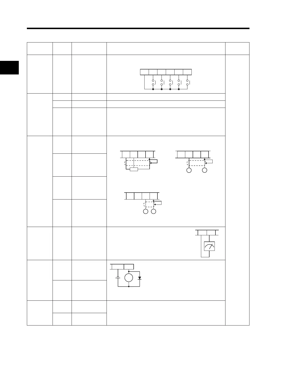
Functions and Connections of the Control Circuit Terminals
*1. Simultaneous input of current and voltage is not possible. Do not connect the signal lines simultaneously.
*2.
By factory default, multi-function output P1 is set to NO contact. To switch to NC contact, change the C031
setting.
Terminal
function
Terminal
symbol
Terminal name Function and connecting method Wire size
Contact
input
(for
switching
function)
S1
S2
S3
S4
S5
Multi-function
input
Select functions and allocate them to terminals S1 to S5.
(The figure below illustrates the wiring of the sink logic.)
Shield wire
of 0.14 to
0.75 mm
2
Recomme
nded wire
size:
0.75 mm
2
Power
supply
P24 Internal 24 V DC 24 V DC output
SC Input common Input signal common
PSC
Input power
supply
If the multi-function input is set as the sink logic, the PSC
terminal acts as an external power supply input terminal.
If the multi-function input terminal is set as the source logic,
the PSC terminal acts as an internal power supply output
terminal.
External
analog
frequency
reference
FS
Frequency
reference power
supply output
• External voltage directive is 0 to 9.8 V.
(Nominal input: 10 V)
*1
FV
Frequency
reference Input
(Voltage
directive)
FI
Frequency
reference Input
(Current
directive)
FC
Frequency
reference
common
Monitor
output
AM
Multi-function
analog output
• Choose from frequency or output current.
Output terminal specifications
0 to 10 V DC full-scale
1 mA max.
Open
Collector
Output
P1
Multi-function
output
*2
Output terminal specifications
Open collector output
27 V DC max.
50 mA max.
Select the status of the Inverter and allocate it to terminal P1.
PC
Multi-function
output common
Relay
output
MA
MB
Relay output
Selection of functions is the same as the multi-function
output.
*3 *4
MC
Relay output
common
SC S5 S4 S3 S2 S1
FS FV FI FC
Variable resistor
(1/2 W min.)
1 to 2 kΩ
FS
FV
FI
FC
+
-
0 to 9.8 V DC
(Nominal input: 10 V)
Input impedance 10
FS
FV
FI
FC
-
+
4 to 19.6 mA DC
Nominal in
ut: 20 mA
AM
SC
PC
P1
RY