2-8
2-2 Wiring
2
Design
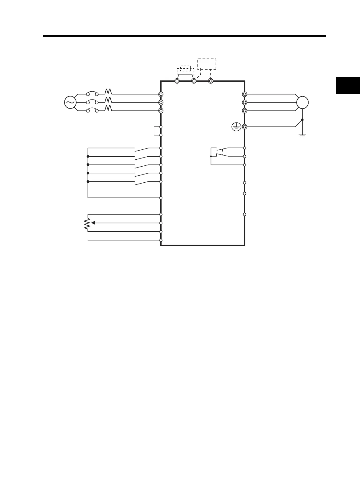
Standard Connection Diagram
Regenerative
braking unit
DC reactor
(optional)
3-phase 200 V AC
1/3-phase 200 V AC *2
3-phase 400 V AC
Multi-function input 1
Multi-function input 2
Multi-function input 3
Multi-function input 4
Multi-function input 5
Frequency reference power supply
Frequency
reference
(1 to 2 kΩ)
Frequency reference input (voltage)
Frequency reference input (current)
*1. The items in parentheses indicate terminal symbols for 3G3JX-AE.
*2. Connect a single-phase 200-V AC input to terminals L1 and N/L3.
*3. By factory default, MA is set to NC contact, and MB to NO contact in the
relay output (MA, MB) contact selection (C036).
Frequency reference common
Sequence input common
M
R/L1 (L1) *1
+1 P/+2 N/-
T/L3 (N/L3)
S/L2 (L2)
U/T1
W/T3
P1
PC
Multi-function output
Multi-function output common
AM Analog monitor output
Relay output *3
Common
V/T2
PSC
P24
S2
S1
S5
SC
FS
FI
FC
FV
S4
S3
MB
MA
MC