4-63
4-2 Function Mode
4
Functions
Signal During RUN
This function outputs a signal while the Inverter is running.
•Also outputs a signal during DC injection braking. Below is the time chart.
Frequency Arrival Signal
This function outputs a signal when the output frequency has reached the set value.
•For elevating machines, use this signal for applying the brake.
07 FBV: PID FB status output PID FB status output 4-67
08 NDc: Network error Network error 4-68
09 LOG: Logic operation output Logic operation result output 4-69
10 ODc: Do not use.
——
43 LOC: Light load detection signal Light load detection signal 4-70
Data Description Reference item Page
Data Symbol Function name Status Description
00 RUN Signal during RUN
ON The Inverter is in RUN mode.
OFF The Inverter is in STOP mode.
Available input terminals P1-PC, MA-MC (or MB-MC)
Required settings C021, C026
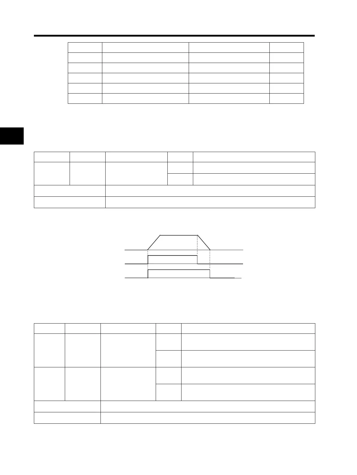
Output frequency
FW
RUN output
Data Symbol Function name Status Description
01 FA1
Constant speed
arrival signal
ON
The Inverter output frequency has reached the F001
set value.
OFF
The Inverter output frequency has fallen below the
F001 set value.
02 FA2
Over set frequency
arrival signal
ON
The Inverter output frequency has exceeded the C042
set value during acceleration.
OFF
The Inverter output frequency has fallen below the
C042 set value during acceleration.
Available input terminals P1-PC, MA-MC (or MB-MC)
Required settings C021, C026, C042, C043