2-15
2-2 Wiring
2
Design
Explanation of the Main Circuit Terminal Connection
* For 3G3JX-AE's terminal symbols, R/L1 corresponds to L1, S/L2 to L2, and T/L3 to N/L3.
Connect a single-phase 200-V AC input to terminals L1 and N/L3.
Model
(3G3JX-)
A2002 to A2007
AE002 to AE004
A2015 to A2037
A4004 to A4037
AE007 to AE022
A2055 to A2075
A4055 to A4075
Screw size W (mm) Screw size W (mm) Screw size W (mm)
Main circuit M3.5 7.1 M4 9.2 M5 13
Control circuit M2 ⎯ M2 ⎯ M2 ⎯
Relay M2.5 ⎯ M2.5 ⎯ M2.5 ⎯
Ground M4 ⎯ M4 ⎯ M5 13
Screw Tightening Torque
Screw Tightening torque
M2 0.2 N•m (max. 0.25 N•m)
M2.5 0.5 N•m (max. 0.6N•m)
M3.5 0.8 N•m (max. 0.9 N•m)
M4 1.2 N•m (max. 1.3 N•m)
M5 3.0 N•m (max. 3.3 N•m)
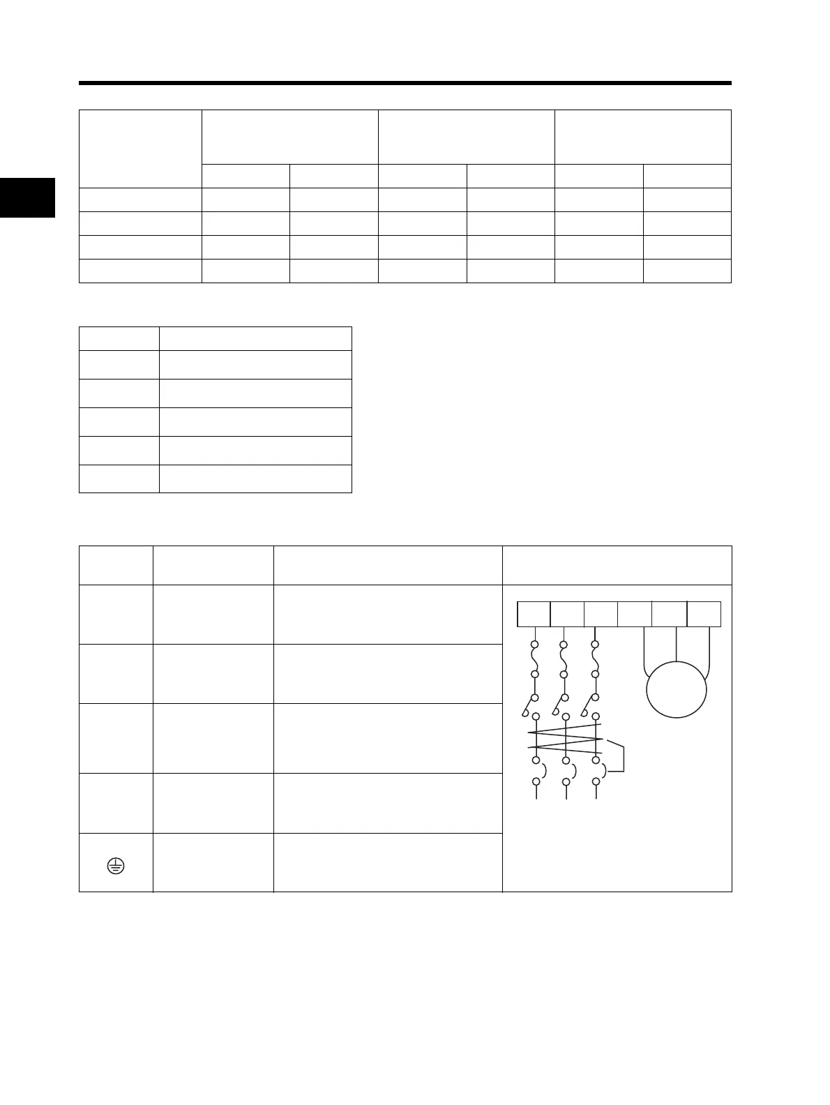
Terminal
symbol
Terminal name Function Connection example
R/L1, S/L2,
T/L3 *
Main power supply
input terminal
Connect the input power supply.
Do not remove the short-circuit bar
between +1 and P/+2 when a DC
reactor is not connected.
U/T1,
V/T2, W/T3
Inverter output
terminal
Connect to the motor.
+1,
P/+2
External DC reactor
terminal
Normally connected by the short-circuit
bar. Remove the short-circuit bar
between +1 and P/+2 when a DC reactor
is connected.
P/+2, N/-
Regenerative
braking unit
connection terminal
Connect optional regenerative braking
units.
(If a braking torque is required)
Ground terminal
Ground (Connect to ground to prevent
electric shock and reduce noise.)
Power supply
ELB
Motor