4-91
4-2 Function Mode
4
Functions
Register Number List
R/W in the list shows whether the coil or holding register accepts reading and/or writing.
R: Read only R/W: Read and write enabled
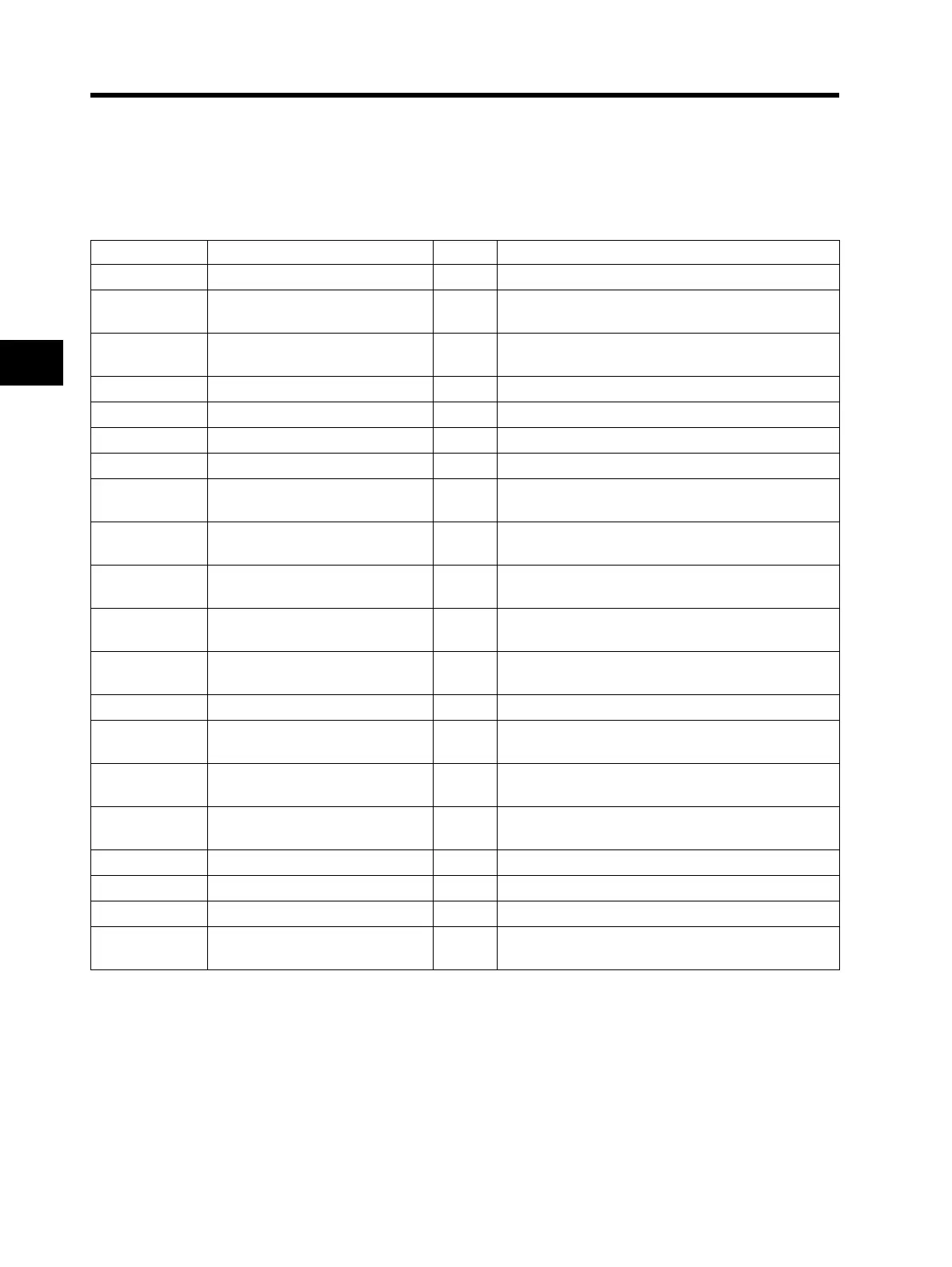
Coil Number List
Coil No. Item R/W Description
0000h Not used ⎯
0001h RUN commands R/W
1: RUN
0: Stop (Enabled when A002 = 03)
0002h Rotation direction command R/W
1: Reverse
0: Forward (Enabled when A002 = 03)
0003h External Trip (EXT) R/W 1: Trip
0004h Trip reset (RS) R/W 1: Reset
0005h Not used ⎯
0006h Not used ⎯
0007h Multi-function input 1 R/W
1: ON
0: OFF
*1
0008h Multi-function input 2 R/W
1: ON
0: OFF
*1
0009h Multi-function input 3 R/W
1: ON
0: OFF
*1
000Ah Multi-function input 4 R/W
1: ON
0: OFF
*1
000Bh Multi-function input 5 R/W
1: ON
0: OFF
*1
000Dh Not used
000Eh Operation status R
1: RUN
0: Stop (Interlocked with d003)
000Fh Rotation direction R
1: Reverse
0: Forward (Interlocked with d003)
0010h Inverter ready R
1: Ready
0: Not ready
0011h Not used ⎯
0012h Not used ⎯
0013h Not used ⎯
0014h Alarm signal R
1: During trip
0: Normal
*1. When either the control circuit terminal block or the coil is turned ON, these settings are ON.
The control circuit terminal block has the priority for the multi-function input.
If the master cannot reset the coil ON status due to communication disconnection, turn the control circuit
terminal block from ON to OFF in order to turn OFF the coil.
*2. The content of a communications error is retained until a fault reset is input. (Available to reset during
operation)