2-11
2-2 Wiring
2
Design
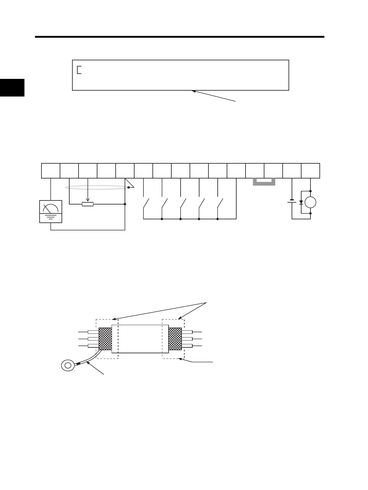
Wiring Example of the Control Circuit Terminal Block (Sink Logic)
Note 1: When connecting a relay to the multi-function output terminal, install a surge-absorbing
diode in parallel with the relay. The output circuit can break down due to surge voltage when
the relay is switched on/off.
Note 2: Remove the short-circuit bar when the external power supply is used.
Note 3: For the signal line, use a twisted shield wire and apply the shield coating as illustrated
below. Keep the length to 20 m or less.
Note 4: Keep the wiring away from the power cable of the main circuit and from the wiring on the
relay control circuit. (More than 10 cm apart)
Input common
Reset input
Multi-step speed reference 2
Frequency meter
Variable resistor
frequency reference
(1 to 2 k)
Short-circuit bar
(at sink logic
[when internal
power supply is
used])
RY
Frequency arrival signal
(27 V DC 50 mA max.)
Multi-step speed reference 1
Reverse rotation RUN command
Forward rotation RUN command
External power supply
terminal for input signal
At sink logic (NPN) : External power supply input
At source logic (PNP) : Power supply output
Note: By factory default, the input logic of the multi-function input terminal circuit is
set to the sink logic.
AM
FS FV FI FC S5 S4 S3 S2 S1 SC
PSC P24
PC P1
Ground connection is not required.
Connect to the ground terminal of the Inverter.
Perform insulating treatment.