7-6
7-3 Connection Example
7
Specifications
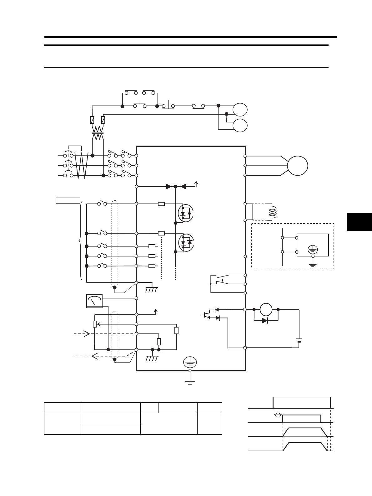
7-3 Connection Example
*1. Different terminals have different commons.
Terminals S1, S2, S3, S4, S5 AM FS, FV, FI P1
Commons
Sink logic - SC
FC PC
Source logic - PSC
BS BSS
MC1
*4
*3
T
MC1
ELB
3-phase
AC
Inverter
R/L1 (L1)
S/L2 (L2)
T/L3 (N/L3)
PSC
24 V DC
U/T1
V/T2
W/T3
Motor
Note:
To connect the DC reactor,
remove the short-circuit bar.
For Sink logic
S5
4.7 kΩ
S4
S3
S2
S1
SC
+1
DC reactor
(Inverter)
P/+2
N/-
P/+2
N/-
Regenerative
braking unit
P/+
N/-
P1
24 V DC
PC
10 kΩ
250 Ω
10 V DC
FC
FI
FV
FS
AM
Frequency
meter
Frequency
setting unit
1 to 2 kΩ
4 to 20 mA DC
Power supply input
Relay output
Common
MB
MA
MC
MC1 MC2
MC2
Alarm wiring in
the regenerative
braking unit
*1
*2
*5
*1
*1
*1
*6
*7
MC2
RY
Main circuit power supply
RUN command
Output frequency
Motor rotation speed
*4
2.0 s min.