4-92
4-2 Function Mode
4
Functions
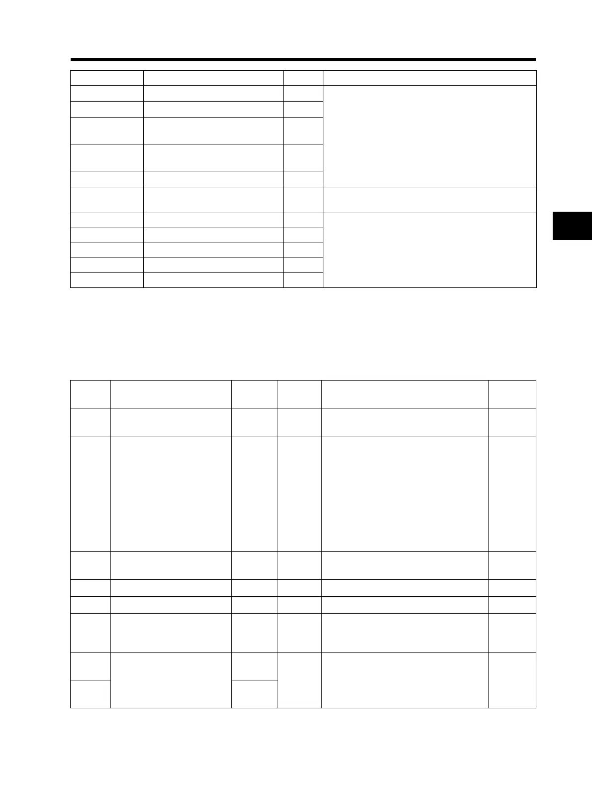
Holding Register Number List
0015h Excessive PID deviation signal R
1: ON
0: OFF
0016h Overload warning signal R
0017h
Frequency arrival signal
(Over set frequency)
R
0018h
Frequency arrival signal
(At a constant speed)
R
0019h Signal during RUN R
001Ah Data writing R
1: Writing
0: Normal
001Bh CRC error R
1: Error
0: No error
*2
001Ch Overrun error R
001Dh Framing error R
001Eh Parity error R
001Fh Check sum error R
Coil No. Item R/W Description
*1. When either the control circuit terminal block or the coil is turned ON, these settings are ON.
The control circuit terminal block has the priority for the multi-function input.
If the master cannot reset the coil ON status due to communication disconnection, turn the control circuit
terminal block from ON to OFF in order to turn OFF the coil.
*2. The content of a communications error is retained until a fault reset is input. (Available to reset during
operation)
Register
No.
Function name
Parameter
No.
R/W
Function
Monitor or data range
Resolution
0002h
Frequency reference
(Enable when A001 = 03)
⎯ R/W 0 to 4000 0.1 [Hz]
0003h Inverter status ⎯ R
00: Default
01: (Reserved)
02: Stop
03: Run
04: Free-run stop (FRS)
05: Jogging
06: DC injection braking
07: Retry
08: Trip
09: Undervoltage
⎯
0005h
PID feedback
(Enable when A076 = 02)
⎯ R/W 0 to 1000 0.1 [%]
1002h Output frequency monitor d001 R 0 to 4000 0.1 [Hz]
1003h Output current monitor d002 R 0 to 2000 0.1 [%]
1004h Rotation direction monitor d003 R
00: Stop
01: Forward
02: Reverse
1005h
PID feedback value monitor
(A075 PID scale)
d004
(MSB)
R 0 to 999900 0.01 [%]
1006h
d004
(LSB)