3-25
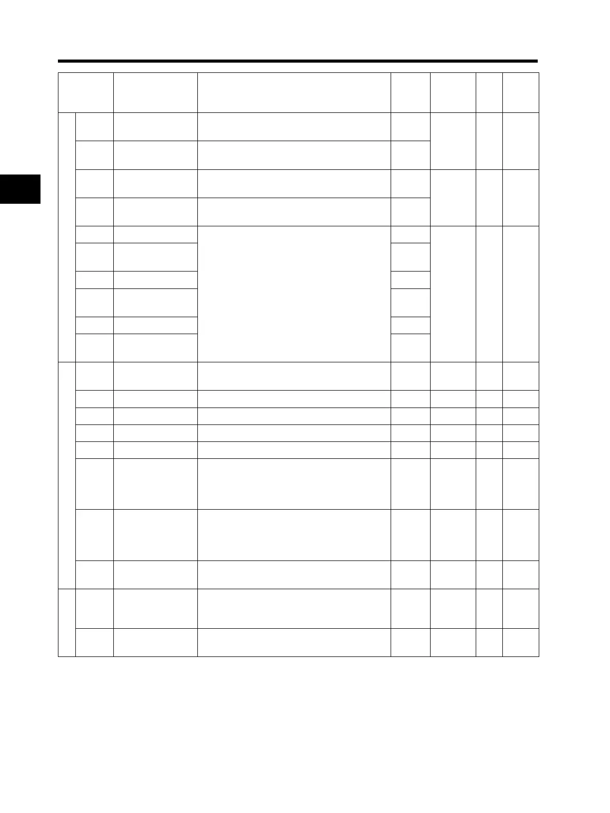
3-7 Parameter List
3
Operation
Upper/Lower limit, Jump
A061
Frequency upper
limit
0.0/Frequency lower limit to Max. frequency 0.0
No Hz 4-19
A261
*2nd frequency
upper limit
0.0/Frequency lower limit to 2nd Max.
frequency
0.0
A062
Frequency lower
limit
0.0/Starting frequency to Frequency upper
limit
0.0
No Hz 4-19
A262
*2nd frequency
lower limit
0.0/Starting frequency to 2nd frequency upper
limit
0.0
A063 Jump frequency 1
Jump frequency: 0.0 to 400.0
Jump frequency width: 0.0 to 10.0
0.0
No Hz 4-19
A064
Jump frequency
width 1
0.5
A065 Jump frequency 2 0.0
A066
Jump frequency
width 2
0.5
A067 Jump frequency 3 0.0
A068
Jump frequency
width 3
0.5
PID control
A071 PID selection
00: Disabled
01: Enabled
00 No ⎯ 4-20
A072 PID P gain 0.2 to 5.0 1.0 Yes ⎯ 4-20
A073 PID I gain 0.0 to 150.0 1.0 Yes s 4-20
A074 PID D gain 0.00 to 100.0 0.0 Yes s 4-20
A075 PID scale 0.01 to 99.99 1.00 No
Time
4-20
A076
PID feedback
selection
00: FI
01: FV
02: RS485 communication
10: Operation function output
00 No ⎯ 4-20
A077
Reverse PID
function
00: OFF (Deviation = Target value - Feedback
value)
01: ON (Deviation = Feedback value - Target
value)
00 No ⎯ 4-20
A078
PID output limit
function
0.00 to 100.0 0.0 No % 4-20
AVR
A081 AVR selection
00: Always ON
01: Always OFF
02: OFF during deceleration
02 No ⎯ 4-23
A082
AVR voltage
selection
200-V class: 200/215/220/230/240
400-V class: 380/400/415/440/460/480
200/
400
No V 4-23
Parameter
No.
Function name
Monitor or data range
(Digital Operator)
Default
setting
Changes
during
operation
Unit Page
* 2nd control is displayed when SET (08) is allocated to one of from C001 to C005.