Multi-function Compact Inverter 3G3MX2-EV2 User’s Manual (I666-E1)
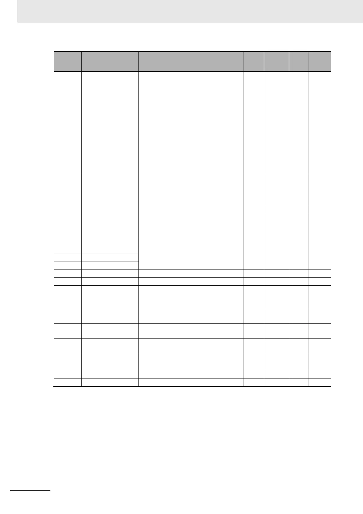
Frequency
Reference Source
Monitor
00: Digital Operator (F001)
01 to 15: Multi-step speed frequency 1 to
15
16: Jogging frequency
18: Modbus communication
19: Option
21: Volume
22: Pulse train frequency
23: Operation function output
24: DriveProgramming
25: Analog voltage input (O)
26: Analog current input (OI)
27: Analog Input (O) + (OI)
RUN Command
Source Monitor
1:
Control circuit terminal block
2: Digital Operator
3: Modbus communication
4: Option
Fault Factor
• Output frequency [Hz]
*1
• Output Current [A]
• Main circuit DC voltage [V]
• Total RUN Time [h]
• Total Power ON Time [h]
Regenerative Brak-
ing Load Rate Moni-
tor
Electronic Thermal
Load Rate Monitor
Analog Voltage Input
O Monitor
0 to 1023 (1023= Equivalent to A/D con-
verter output of 10.9 V)
Analog Current Input
OI Monitor
0 to 1023 (1023= Equivalent to A/D con-
verter output of 23.3 mA)
Pulse Train Input EA
Monitor
*1. When the frequency is displayed, in high-frequency mode, the operator display resolution becomes 0.1
(equivalent to the 3G3MX2-E Series Inverter).
*2. The digit shift display mode can be used.