⚫
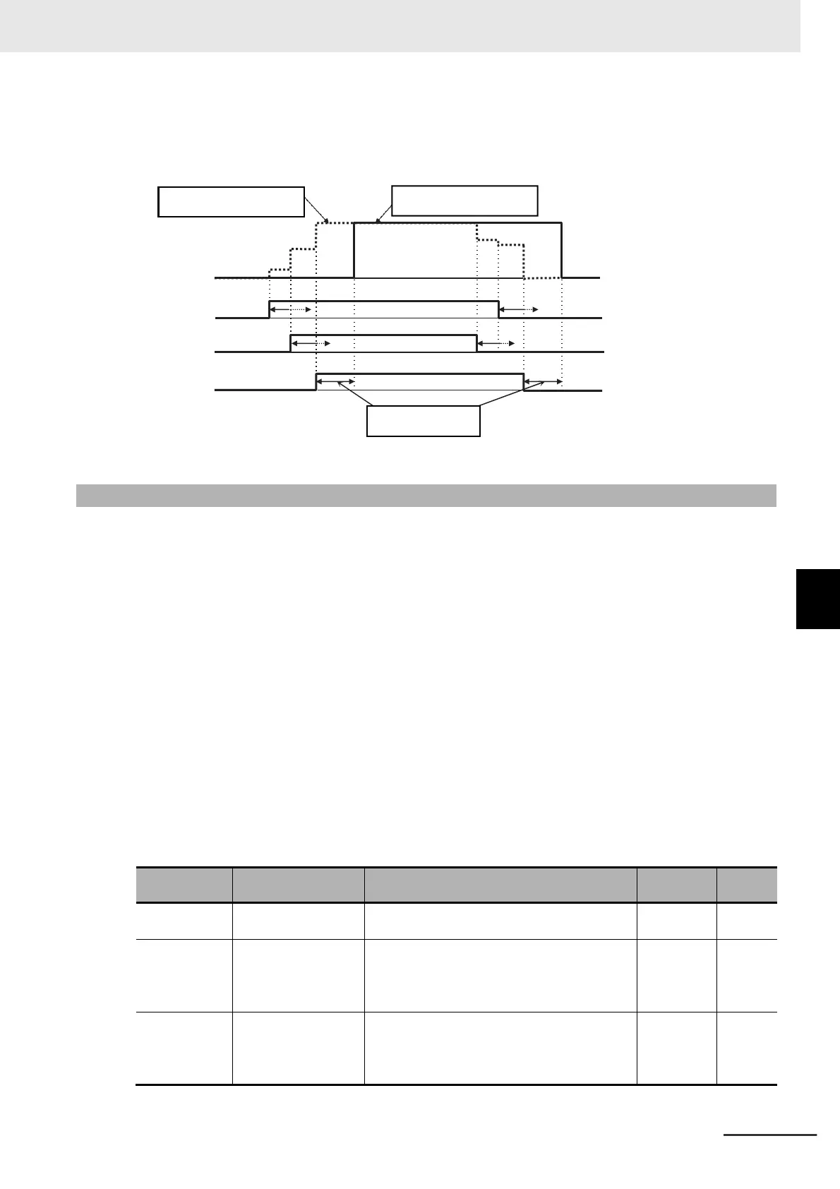
Operation Diagram for Multi-step Speed/Position Determination Time (C169)
The inverter recognizes the input data when the time set in C169 elapsed since it detected the sta-
tus transition of the last input signal.
7
3
Position command
1
With determination time
(C169)
5
4
CP1
CP2
CP3
6-7-7 Turntable Control
This function is useful when using a system of rotating coordinates such as those of a turn table.
It performs positioning based on the amount of movement per rotation of the rotating coordinates in the
direction in which the moving distance is shorter.
•
Set the Position Control Mode Selection (P075) to 01 (No limit).
•
Set the amount of movement per rotation of the rotating coordinates in the Multi-step Position Com-
mand 0 (P060).
This value must be set as 1 multiplication pulses (equivalent the number of phase-A pulses) and a
positive value.
•
In the Multi-step Position Command 1 to 7 (P061 to P067), set the actual target positions.
These values must be set as 1 multiplication pulses (equivalent the number of phase-A pulses).
•
This control is enabled when the Pulse Train Input Type Selection (P004) is set to 00 (Single-phase
pulse input) or 01 (Phase A and B 90° phase difference pulse train). Do not use this control with the
set value 03 (Single-phase pulse train + direction).
•
The origin search, current position preset, and speed/position switching functions do not work when
the Position Control Mode Selection (P075) is set to 01 (No limit).
Do not use the turntable control function in conjunction with the origin search, current position preset,
or speed/position switching function.
Position Limit Setting (Reverse Side) (P073) to
Position Limit Setting (Forward Side) (P072)
*1
(Displays upper 5 digits excluding “-”)
(1 multiplication)
Position Limit Setting (Reverse Side) (P073) to
Position Limit Setting (Forward Side) (P072)
*1
(Displays upper 5 digits excluding “-”)
(1 multiplication)