Overview of Braking Resistor Selection
If the regenerative energy generated in deceleration or
descent in an application is too large, the main circuit voltage
in the inverter may increase, which results in damage to the
inverter.
Normally, the inverter has a built-in overvoltage protection
function, which detects an overvoltage (0 V) in the main
circuit to prevent inverter damage. However, because it
detects a fault to stop the motor, stable and continuous
operation will be prevented.
Therefore, you need to use one or more braking resistors/
regenerative braking units to absorb this regenerative energy
outside the inverter.
What is Regenerative Energy?
The load connected to a motor has kinetic energy when
rotating, and potential energy when it is subject to the gravity.
When the motor decelerates, or when the load descends, the
energy is fed back to an inverter. This phenomenon is known
as regeneration, and the energy is called regenerative
energy.
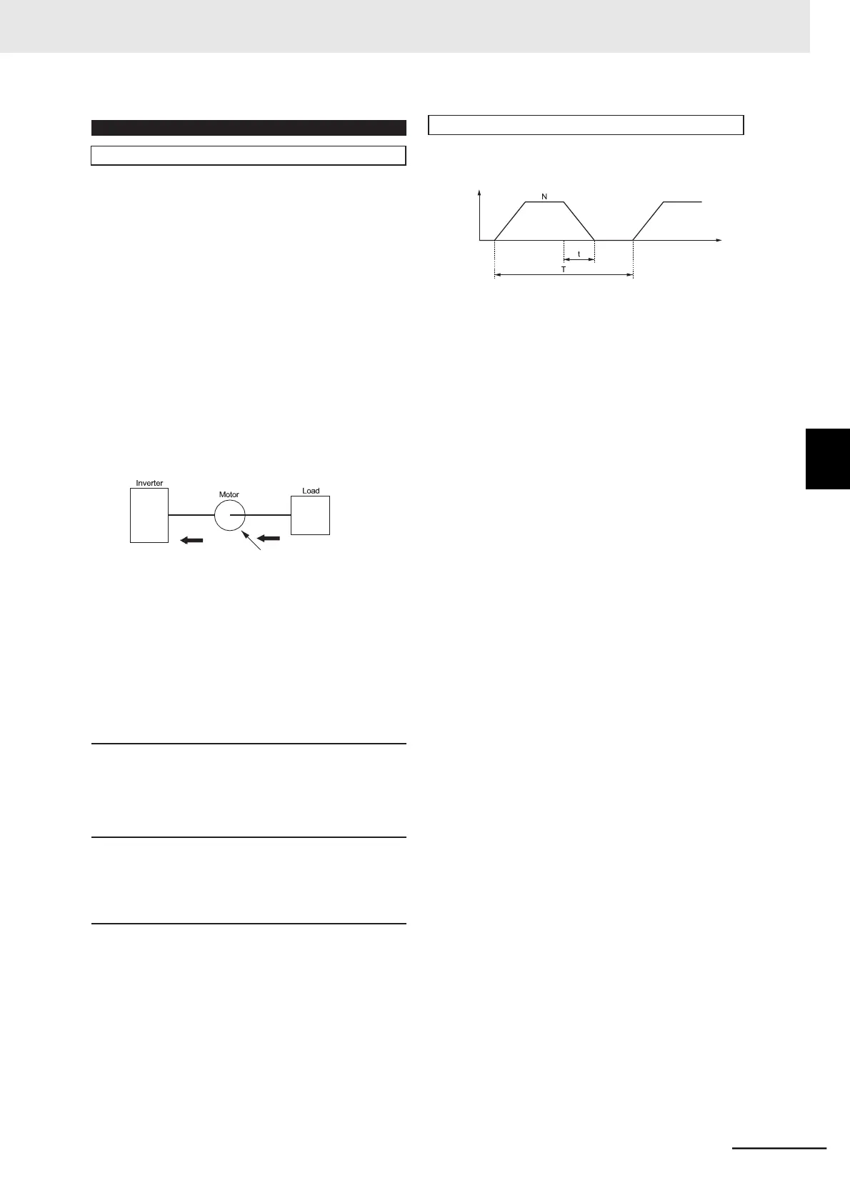
This is a simple method to select an appropriate braking resistor
based on the percentage of the time in which regenerative energy
is produced in a normal operation pattern.
[r/min]
Time
• Usage rate [%ED] = 100 x t/T
t: Deceleration time (regenerative time) [s]
T: 1cycle operation time [s]
For models with built-in regenerative braking circuit
All models of the 3G3MX2-EV2 Series Inverter have built-
in regenerative braking circuit.
Select a braking resistor based on the usage rate
calculated from the operation pattern.
Connect a braking resistor suitable for your inverter
according to the braking resistor list provided in the
inverter manual/catalog.
Regenerative
energy
Kinetic energy
Potential energy
When decelerating, the motor serves
as a generator to convert the kinetic/
potential energy into regenerative energy.
For models without built-in regenerative braking circuit
If a braking torque or regenerative energy is extremely
large, even the 3G3MX2-EV2 Series Inverter may
require the Regenerative Braking Unit.
Select an appropriate regenerative braking unit and
braking resistor.
Preventing an overvoltage (0 V) in the main circuit without use
of braking resistors
The following are methods to prevent the occurrence of an
overvoltage (0 V) in the main circuit without connection of
braking resistors.
Since these methods prolong the deceleration time, check
that the selected method will not cause application problems.
• Enable the Overvoltage Suppression Function during
Deceleration
The Overvoltage Suppression Function during Deceleration
is enabled by default.
It automatically increases the deceleration time to prevent
the occurrence of an overvoltage in the main circuit.
• Set a longer deceleration time
Increase the deceleration time to prevent the occurrence of
an overvoltage in the main circuit.
This decreases the amount of regenerative energy per unit
time.
• Select free-run stop
This prevents the regenerative energy from being fed back
to the inverter.
Connect a regenerative braking unit and braking resistor
suitable for your inverter according to the regenerative
braking unit/braking resistor list provided in the inverter
manual and catalog.