83
Serial Gateway Overview Section 3-6
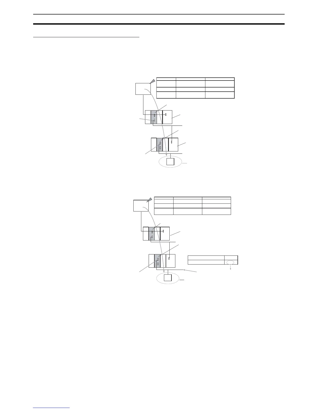
Serial-to-Serial-to-Serial Conversion
Routing tables to enable the serial communications path to be treated as a
network are optional.
Without Routing Tables
Specify the addresses as shown in the following example.
With Routing Tables
Specify the addresses as shown in the following example.
Address Specification
Address Contents Example
s+1
Serial Communications Unit/Board
E.g., Unit number 2, port 1
Serial Communications Unit/Board
E.g., Unit number 0, port 1
Target: OMRON Component or Modbus Slave
PLC_1
PLC_2
CPU Unit
CPU Unit
FINS
command
sent
Remote net-
work address
Remote node
address
Remote unit
address
PC_1 serial port
unit address
PC_2 unit number for
Host Link + 1
PC_2 serial port
unit address
89 hex (137 decimal)
Calculated from PC_1 unit
number 2, port 2
80 hex (128 decimal)
Calculated from unit number
0, port 1
Serial communications
path (Host Link FINS)
(1) Network address:
To PLC_1 serial port
unit address (e.g., 89
No routing tables required to treat serial
communications path as a network
Serial communications
path (Host Link FINS)
No routing tables required to treat serial
communications path as a network
(2) Node address: PLC_2
unit numbers for Host Link
(0 to 31) + 1
(3) Unit address: To
PLC_2 serial port unit
address (e.g., 80 hex)
Serial communications path
(CompoWay/F, Modbus)
Address Contents Example
A
s+1
PC_2 serial port unit address
Serial Communications Unit/Board
E.g., Unit number 2, port 1
Serial Communications Unit/Board
E.g., Unit number 0, port 1
Target: OMRON Component or Modbus Slave
Unit number
80 hex (128 decimal)
Calculated from unit number 0, port 1
A
CPU Unit
Address Specification
PLC_2
PLC_1
CPU Unit
FINS
command
sent
Serial communications
path (Host Link FINS)
Remote network
address
Remote node
address
Remote unit
address
PC_2 serial communications
path network address A
PC_2 unit number for Host
Link + 1
80 hex (128 decimal)
Calculated from unit number
0, port 1
No routing tables required to treat serial
communications path as a network
Routing tables for treating serial
communications path as a network
Serial communications
path (Host Link FINS)
(2) Node address:
PLC_2 unit numbers for
Host Link (0 to 31) + 1
(3) Unit address:
To PLC_2 serial port unit
address (e.g., 80 hex)
Network
address
Serial communica-
tions path (Compo-
Way/F, Modbus)
(1) Network address: To PLC_1 serial
communications path network address A
 Loading...


