92
Communications Frames Section 3-7
List of Settings
• FINS Network Settings
Item Value
(Example)
Setting location
Send destination network
address
(Controller Link network
address of PC to which
Serial Communications Unit
is mounted)
2 Set 02 hex in the control data
C+2 bits 00 to 07 (network
address) of CMND(490).
Note: Set 0 hex in the control
data C+2 bits 08 to 11 (serial
port number) of CMND(490).
Send destination node
address
(node address in Controller
Link for PC to which Serial
Communications Unit is
mounted)
5 Set 05 hex in the control data
C+3 bits 08 to 15 (send destina-
tion node address) of
CMND(490).
Serial Communications Unit
unit number
3 Use to calculate the following
unit address for the serial port
80 hex + 4 hex
× unit number 3
= 8C hex
Serial Communications Unit
serial port
Port 1
Send destination unit
address
(unit address of serial port
on Serial Communications
Unit)
80 hex + 4 hex
×
unit number 3 = 8C
hex (or 10 + unit
number 3 - 13 hex,
and serial port num-
ber 1 = 1 hex)
Set 8C hex in the control data
C+3 bits 00 to 07 (send destina-
tion unit address) of CMND(490).
(Alternatively, set 13 hex in the
control data C+3 bits 00 to 07
(send destination unit address)
and set 1 hex in C+2 bits 08 to 11
(serial port number).)
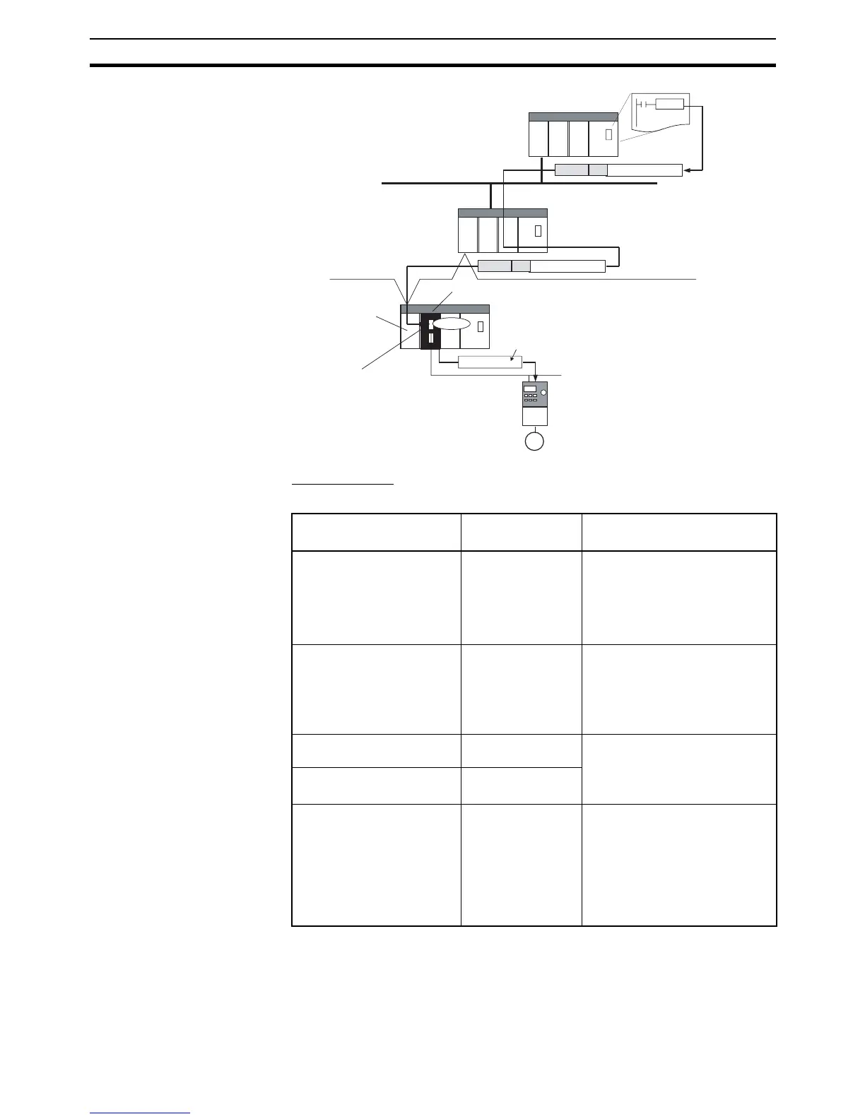
2804
FINS header
Network (Ethernet)
FINS message
Modbus-RTU command
FINS message
Network (Controller Link)
Network address: 2
Serial Communications Unit
Unit No. 3, port 1
Conversion Link Unit
Node address: 5
Port 1 unit address:
80 hex + 4 hex × unit number 3 = 8C hex
RS-485 (Modbus-RTU)
3G3MV OMRON Inverter
CPU Unit
CMND
instruction
FINS header
2804
Modbus-RTU command
Protocol
conversion
Modbus-RTU command
Example: Write data for frequency reference value
(FUNCTION code 10 hex, register No. 0002 hex)
 Loading...


