36
Settings for Sending FINS Commands Section 3-4
3-4-2 Addresses in FINS Commands
FINS commands are transmitted across networks and to various devices (via
network nodes). Designate the addresses as follows:
• Designate the device from which the command is to be sent, the network
that the device is on, and the node through which the command is to tran-
sit.
• Designate the device to which the command is to be sent, the network the
device is on, and the node through which command is to transit.
Addresses must be provided for the network, node, and device (unit) to iden-
tify them. FINS commands include these addresses (the transmission source
and destination addresses) in the command/response frames.
Addresses for FINS Commands
Devices on the Same Network
Note 1. The transmission source address will be automatically incorporated into
the frame if the FINS command is sent with CMND(490). If sending the
Address Values Designation method
CMND(490) operand
designation
Designation in frame
when frame is created
Network address 1 to 127 (01 to 7F Hex)
Local node address: 00 Hex
Ye s Ye s
Node address 1 to 254 (01 to FE Hex) (See note.)
Note The node addresses differ for each
network.
Internal Communications in PLC: 00 Hex
For Controller Link: 01 to 3E Hex (1 to 62)
For Ethernet Units with model numbers
ending in ETN21
: 01 to FE Hex (1 to 254)
For Ethernet Units with other model
numbers
: 01 to 7E Hex (1 to 126)
Ye s Ye s
Unit address •CPU Unit: 00 Hex
•CPU Bus Unit: Unit No.+ 10 Hex
•Special I/O Unit: Unit No.+ 20 Hex
•Inner Board: E1 Hex
•Computer: 01 Hex
•Unit connected to network: FE Hex
Ye s Ye s
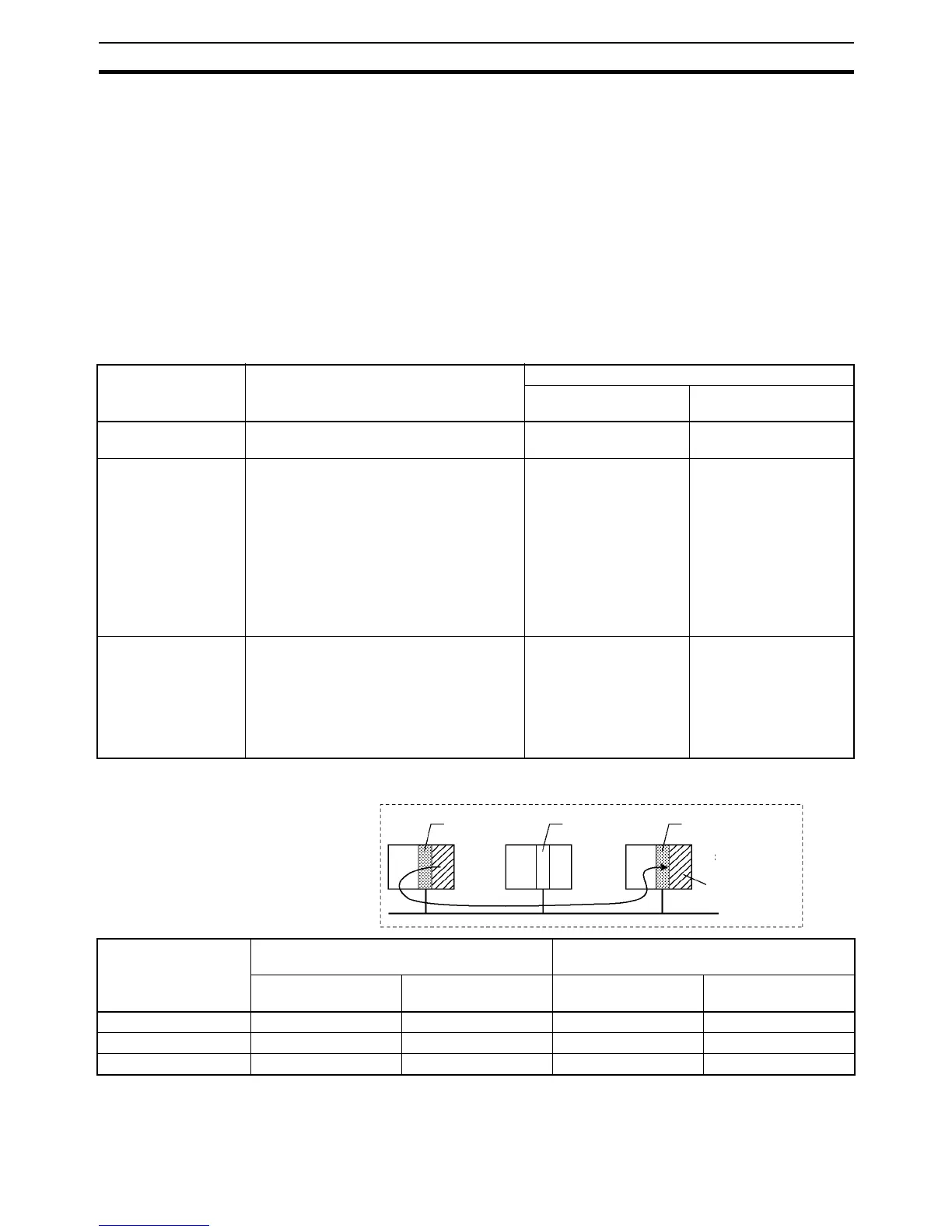
Example
Node address 1
Node address 2
Node address 3
For CPU Unit
(00 Hex)
PLC
PLCPLC
Address Source address (See note 1.) Destination address
(See note 2.)
FINS command
symbol
Example value FINS command
symbol
Example value
Network address SNA 00 Hex DNA 00 Hex
Node address SA1 01 Hex DA1 03 Hex
Unit address SA2 00 Hex DA2 00 Hex