86
Communications Frames Section 3-7
Reasons for Routing Tables
CompoWay/F, Modbus-RTU, Modbus-ASCII Protocol Conversion
Routing tables are not required to enable serial communications paths to be
treated as networks. (The serial port can be specified in the node without
using routing tables by specifying the node to which the Board/Unit is con-
nected, and specifying the unit address as that of the serial port.)
Host Link FINS Protocol Conversion and Use of Network
Routing tables are required to enable the serial communications path to be
treated as a network. This is because with Host Link FINS, the FINS remote
node address is used to specify the target (communications partner PC that is
the Host Link slave). Therefore, the node to which the Board/Unit is mounted
cannot always be specified, depending on the FINS remote node address. To
specify the Unit at the target requires the FINS remote unit address. There-
fore, the serial port cannot always be specified depending on the FINS unit
address.
The network address for the serial communications path is used to specify
from the network the node to which the Board/Unit is mounted and the serial
port. Therefore, routing tables must be used to enable the serial communica-
tions path to be treated as a network.
Host Link FINS Protocol Conversion and Use of Serial Connection
Routing tables are not required to enable serial communications paths to be
treated as networks. The serial port in the node can be specified without rout-
ing tables by specifying the network address as the unit address of the serial
port.
3-7 Communications Frames
3-7-1 CompoWay/F
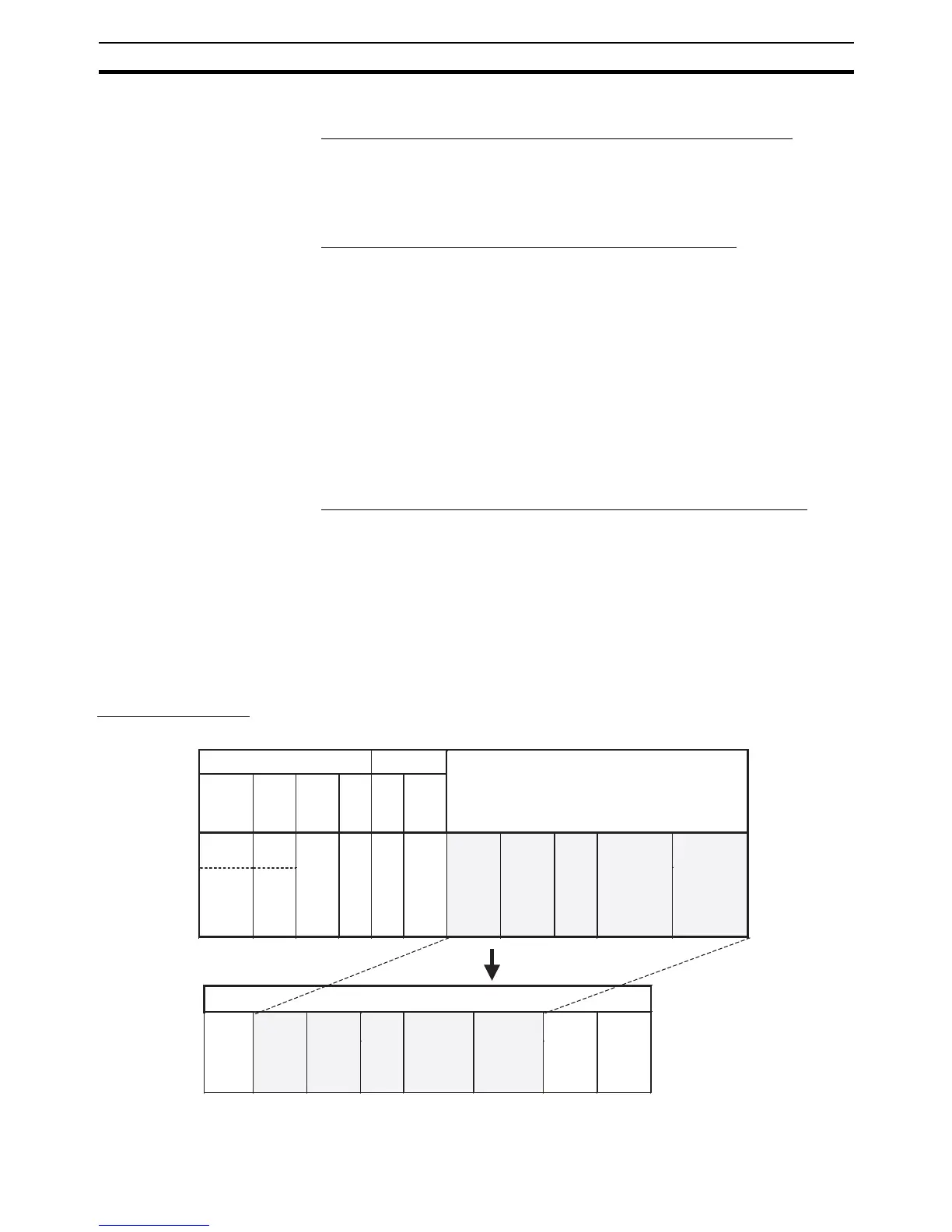
Command Frame
Frame before Conversion
FINS header FINS command
CompoWay/F
(See note.)
MRC SRC
00 hex 28 03
Node No.
(× 10
1
)
(× 10
2
)
(ASCII code
2 bytes)
Sub-
address
"00"
(ASCII code
3030 hex)
etc.
SID
"0"
(ASCII
code
30 hex)
Command
(MRC, SRC)
(ASCII code
4 bytes)
Text
(ASCII code)
CompoWay/F
STX
(02 hex)
Node No.
(× 10
1
)
(× 10
2
)
(ASCII code
2 bytes)
Sub-
address
"00"
(ASCII code
3030 hex)
etc.
BCCETX
(03 hex)
Text
(ASCII code)
Command
(MRC, SRC)
(ASCII code
4 bytes)
SID
"0"
(ASCII
code
30 hex)
Frame after Conversion
Etc.Remote
network
address
(DNA)
Remote
node
address
(DA1)
Remote
unit
address
(DA2)
Serial port
allocated
address
or local
network
address
or local
network
node
address
Serial
port unit
address
 Loading...


