70
Serial Gateway Overview Section 3-6
• With routing tables that treat serial communications path as a network:
Network address corresponding to serial port in the routing tables.
• Without routing tables that treat serial communications path as a net-
work: Network address for specifying actual remote PC.
• Remote destination node address (DA1)
• With routing tables that treat serial communications path as a network:
00 hex (local PC’s internal communications) (For serial-to-serial-to-se-
rial conversion, increment the Host Link unit number by 1.)
• Without routing tables that treat serial communications path as a net-
work: Node address for specifying actual remote PC (For serial-to-se-
rial-to-serial conversion, increment the Host Link unit number by 1.)
• Remote destination unit address (DA2)
Unit address of serial port
(2) The contents of the CompoWay/F command enclosed in the FINS mes-
sage that is sent is as follows:
Node number + subaddress + SID + command text (ASCII must be used.)
STX, ETX+BCC are not required when sending FINS. They are added
automatically for serial communications.
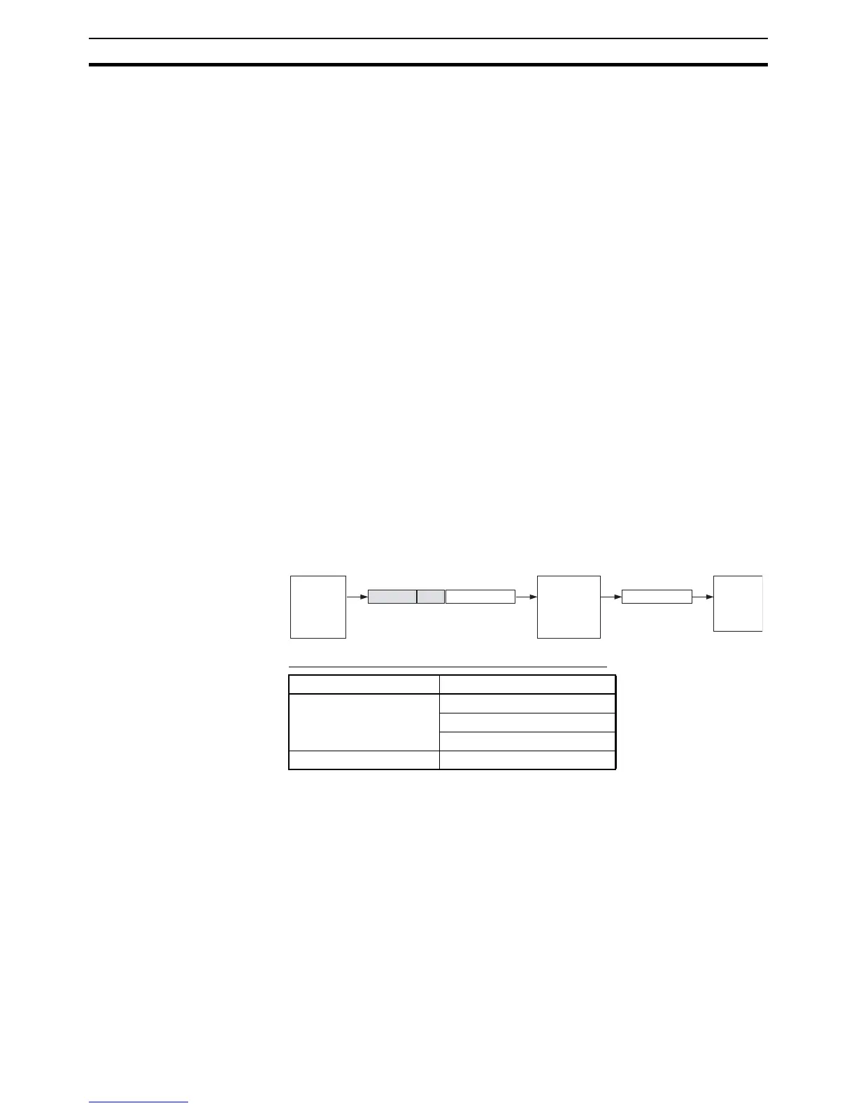
3-6-4 Converting FINS to Modbus-RTU
Modbus-RTU Slave-compatible devices (including OMRON Inverters) con-
nected serially to a PC via Modbus-RTU can be accessed from the PC or PT
using Modbus-RTU commands enclosed in FINS messages.
• Sent FINS message: FINS header + FINS command code 2804 hex +
Modbus-RTU command
• Message after conversion: Modbus-RTU command
Modbus-RTU Slave-compatible OMRON Devices
Type Model series
Inverters 3G3JV
3G3MV
3G3RV
Temperature Controllers E5CN (New version)
FINS header
Modbus-RTU command
2804
(Via network or CPU bus)
Modbus-RTU command
Modbus-RTU command
(RS-232C or RS-422A/485)
CPU Unit
(CMND(490)
instruction) or
PT (Program-
mable Termi-
nal)
Modbus-RTU command encapsulated
using FINS command 2804 hex
Serial Com-
munications
Unit/Board
Modbus-RTU
Slave-
compatible
device
(OMRON
Inverter, etc.)