3
C-mode Commands Section 1-2
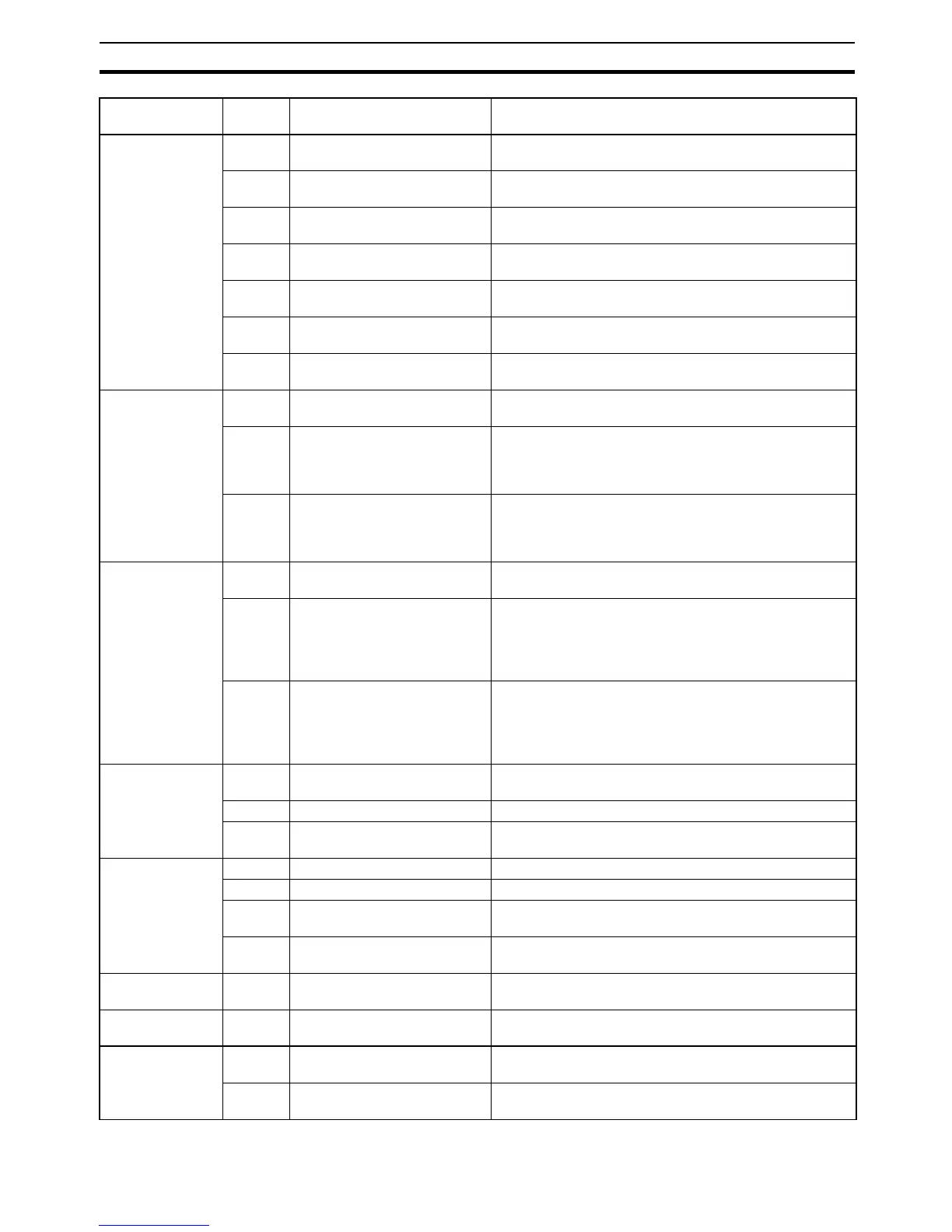
I/O memory
writing
WR CIO AREA WRITE Writes the specified data in word units beginning with the
designated CIO word.
WL LR AREA WRITE Writes the specified data in word units beginning with the
designated LR word.
WH HR AREA WRITE Writes the specified data in word units beginning with the
designated HR word.
WC TIMER/COUNTER PV WRITE Writes the specified timer/counter PV data in word units
beginning with the designated word.
WD DM AREA WRITE Writes the specified data in word units beginning with the
designated DM word.
WJ AR AREA WRITE Writes the specified data in word units beginning with the
designated AR word.
WE EM AREA WRITE Writes the specified data in word units beginning with the
designated EM word.
Timer/counter SV
reading
R# TIMER/COUNTER SV READ
1
Reads in four digits BCD the constant SV that is written as
an operand of the designated timer/counter instruction.
R$ TIMER/COUNTER SV READ
2
Finds the specified timer/counter instruction, beginning
with the designated program address, and reads the con-
stant SV in four digits or the word in which the SV is
stored.
R% TIMER/COUNTER SV READ
3
Finds the specified timer/counter instruction, beginning
with the designated program address, and reads the con-
stant SV in four digits (BCD) or the word in which the SV
is stored.
Timer/counter SV
changing
W# TIMER/COUNTER SV
CHANGE 1
Changes the SV of the specified timer/counter instruction
to a new constant SV.
W$ TIMER/COUNTER SV
CHANGE 2
Finds the specified timer/counter instruction, beginning
with the designated program address in the user program,
and changes the constant SV in four digits (BCD) or the
word in which the SV is stored to a new constant SV or
storage word.
W% TIMER/COUNTER SV
CHANGE 3
Finds the specified timer/counter instruction, beginning
with the designated program address in the user program,
and changes the constant SV in four digits (BCD) or the
word in which the SV is stored to a new constant SV or
storage word.
CPU Unit status MS STATUS READ Reads the CPU Unit’s operating conditions (operating
mode, forced set/reset status, and fatal errors).
SC STATUS CHANGE Changes the CPU Unit’s operating mode.
MF ERROR READ Reads the CPU Unit’s error information (i.e., all fatal or
non-fatal errors currently in effect).
Forced
set/reset
KS FORCED SET Forcibly sets one designated bit.
KR FORCED RESET Forcibly resets one designated bit.
FK MULTIPLE FORCED
SET/RESET
Forcibly sets/resets/cancels multiple designated bits.
KC FORCED SET/RESET CAN-
CEL
Cancels all forced set/reset status.
PLC model code
reading
MM PLC MODEL READ Reads the model code of the CPU Unit.
Testing TS TEST Returns, just as it is, a single block that was sent from the
host computer.
Program area
accessing
RP PROGRAM READ Reads, in one batch, the contents of the CPU Unit’s user
program at the machine language (object) level.
WP PROGRAM WRITE Writes into the CPU Unit’s user program area the
machine language (object) sent from the host computer.
Type Header
code
Name Function