236
FINS Commands Section 5-3
Precautions • FINS Header (Destination Address) Contents
The following settings are required.
• Destination Network Address (DNA):
• When a routing table is created to treat the serial communications path
as a network, this is the network address associated with the Serial
Communications Unit or Board's serial port by the routing table
• When a routing table is not created to treat the serial communications
path as a network, this is the actual network address used to specify
the destination PLC.
• Destination Node Address (DA1):
• When a routing table is created to treat the serial communications path
as a network, set 00 hex for communications within the local PLC or
the “Host Link unit number + 1” for serial → serial → serial conversion.
• When a routing table is not created to treat the serial communications
path as a network, this is the actual node address used to specify the
destination PLC (the “Host Link unit number + 1” for serial → serial →
serial conversion).
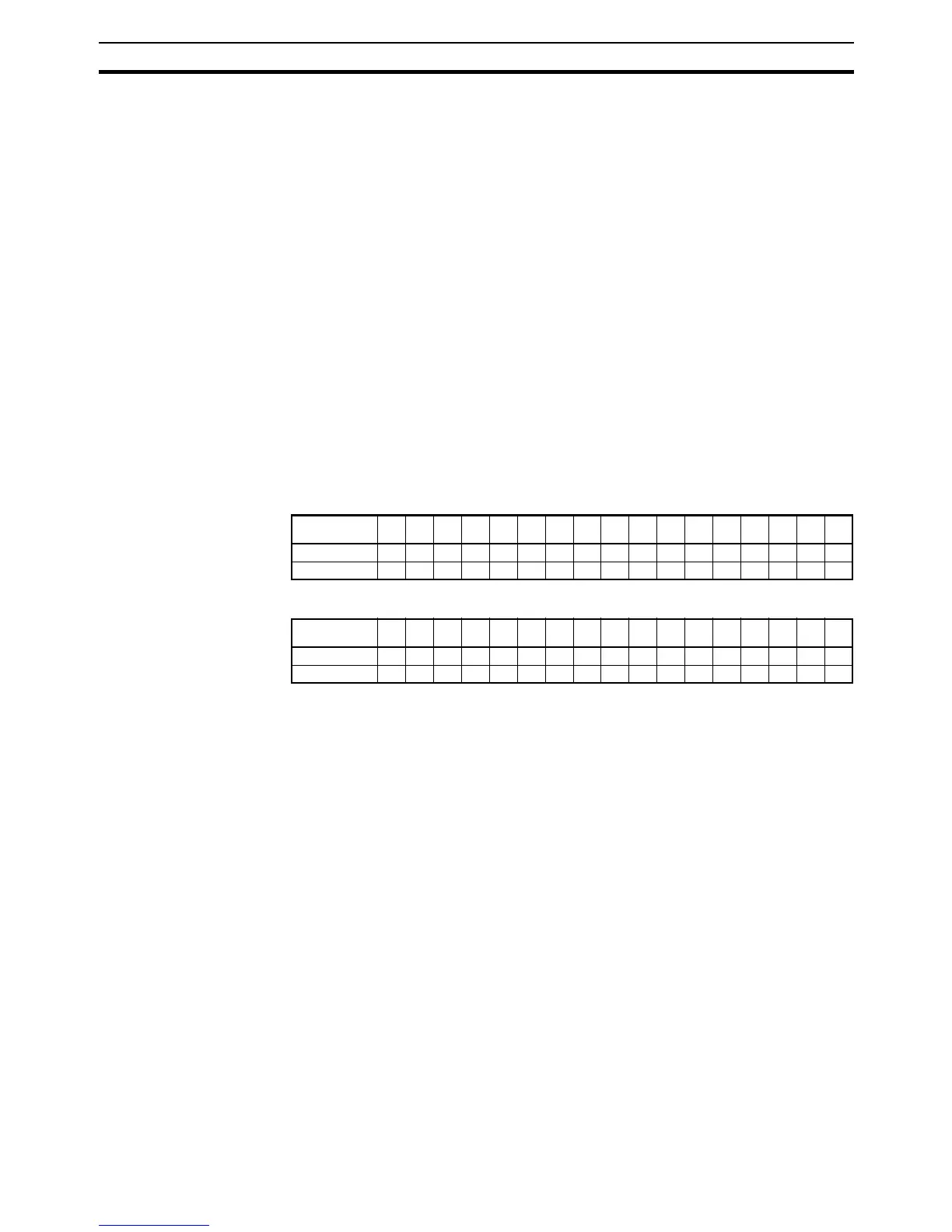
• Destination Unite Address (DA2):
This is the serial ports unit address.
• Unit addresses for serial port 1:
• Unit addresses for serial port 2:
• Sending Modbus-ASCII Commands with the CMND Instruction
• Set FINS command code 2805 hex (CONVERT TO MODBUS-ASCII
COMMAND) in S.
• Set the following parameters in ASCII starting at S+1 with the leftmost
byte first: Slave address (2-byte ASCII), Function code (2-byte ASCII),
and the communications data (ASCII, 2 × n bytes).
Note For Modbus-RTU, set the Modbus-RTU Slave address (1 byte) in the
leftmost byte of S+1 and the function code (1 byte) in the rightmost
byte of S+1.
Unit number0123456789ABCDEFBo
ard
Hexadecimal 80 84 88 8C 90 94 98 9C A0 A4 A8 AC B0 B4 B8 BC E4
Decimal 128 132 136 140 144 148 152 156 160 164 168 172 176 180 184 188 228
Unit number0123456789ABCDEFBo
ard
Hexadecimal 81 85 89 8D 91 95 99 9D A1 A5 A9 AD B1 B5 B9 BD E5
Decimal 129 133 137 141 145 149 153 157 161 165 169 173 177 181 185 189 229
 Loading...


