50
Chapter3
OS32C
User’s Manual
Basic Operation of Configuration Software
• Non-Safety-Critical Parameters
1. Restart Delay : Select the desired OFF-to-ON delay when wiring the OS32C in
Automatic Start. Available range is 100ms to 60s, in increments
of 100ms.
2. Auxiliary Output Mode : Select either Disable, Follow OSSD, Indicate FAULT,
Warning Zone 1 infringed, Warning Zone 2 infringed, or
Window contaminated.
3. Auxiliary output type : Select PNP or NPN.
4. Auxiliary output polarity : Select Active ON or Active OFF.
5. Warning Output Mode : Select either Disable, Follow OSSD, Indicate FAULT,
Warning Zone 1 infringed, Warning Zone 2 infringed, or
Window contaminated.
6. Warning output type : Select PNP or NPN.
7. Warning output polarity : Select Active ON or Active OFF.
8. Power reserve mode : Select either Disabled or Standby mode.
9. Seven-segment display : Select Enable - Non-inverted, Enable - Inverted, or Disable.
When the display is inverted, a decimal will be displayed in the
corner. This display can be disabled to save power. Note: even
if the seven-segment display is disabled, the 4-digit code for
programming a scanner will still be displayed.
10. ISI option : Select Enable or Disable. When enabled, the ISIs will turn ON
to indicate the sector(s) where an intrusion has occured in a
safety or warning zone (depends on the ISI mode, see below).
11. ISI mode : Select Follow safety zone to have the ISIs light up to indicate
the sectors where an intrusion has occurred in the safety zone.
Select Follow warning zone to have the ISIs light up to
indicate the sector(s) where an intrusion has occured in a
warning zone.
The seven segment display can be inverted when the OS32C is installed upside down.
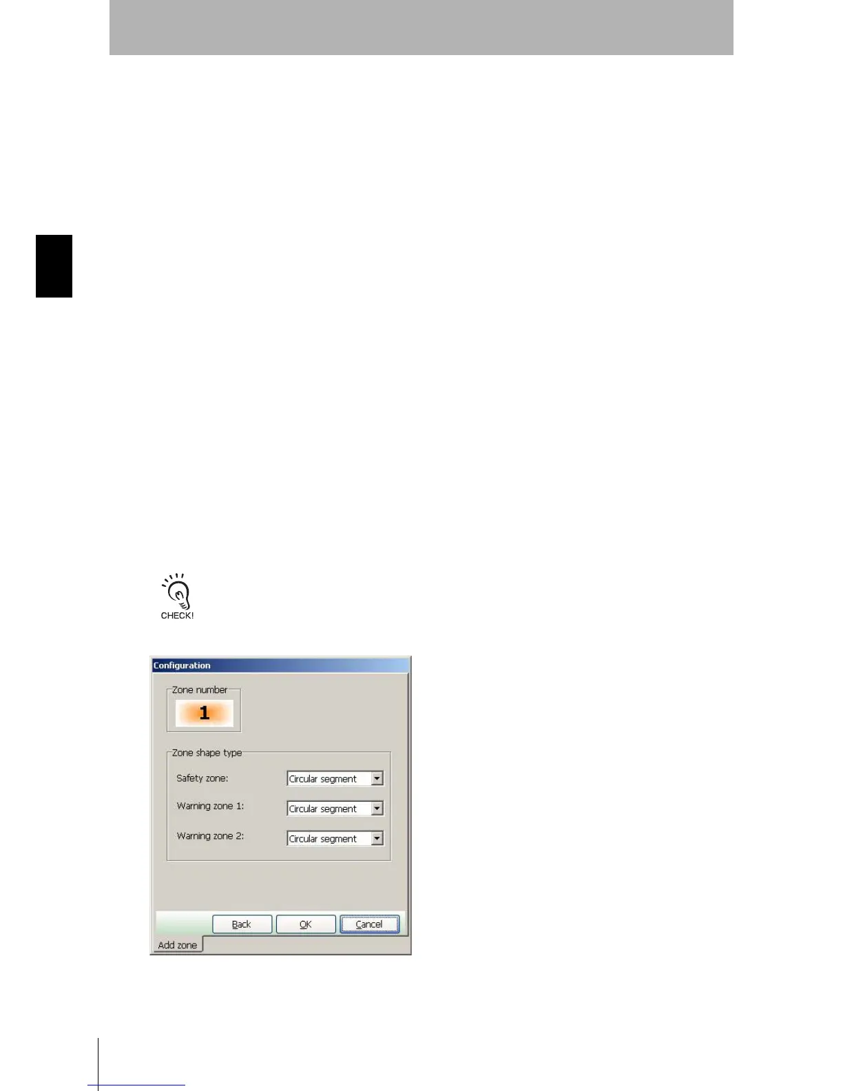
4. After configuration of parameters is finished, click Next.
Fig. 3-19 Zone Shape
 Loading...