34
Wiring Section 2-3
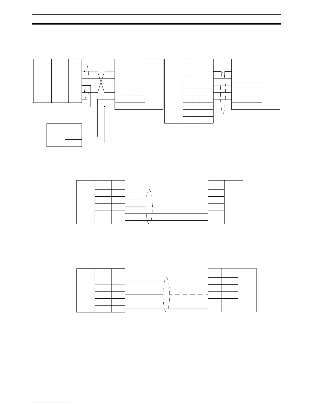
■ 1:N Connections Using RS-232C Port 1
Use the NT-AL001-E Converter Link Adapter
■ 1:1 Connections Using RS-422A/485 Port 2 (MCW151-E only)
Programming Terminal (PT)
Note MC Unit Communication Mode: Host Link Slave
PC (Serial Communication Board)
Note MC Unit Communication Mode: Host Link Master
MC Unit
RS-232C
Interface
Signal Pin
RS-1 2
SD-1 6
SG-1 7
RD-1 8
FG Shell
General Device
Signal
RS-422A
Interface
Frame ground
Signal ground
Receivedata(+)
Receivedata(-)
Send data (+)
Send data (-)
D-sub 9-pin
connector (male)
mini-DIN 8-pin
connector (male)
Pin Signal
RS-232C
Interface
2SD
3RD
4RS
5CS
6+5V
9SG
RS-422A
Interface
Signal Pin
FG 1
SG 2
SDB 3
SDA 4
RDB 5
RDA 6
CSB 7
CSA 8
NT-AL001
Terminal Block
MC Unit
Power
Supply
(5V)
Signal
+
-
MC Unit
RS-422A
Interface
Signal Pin
RD- 1
RD+ 2
FG 3
SD- 4
SD+ 5
Programmable Terminal (PT)
Signal
RS-422A
Interface
SDA
SDB
-
RDA
RDB
COMBICON
Plug
Terminal Block
MC Unit
RS-422A
Interface
Signal Pin
RD- 1
RD+ 2
FG 3
SD- 4
SD+ 5
PC
Pin Signal
RS-422A
Interface
1SDA
2SDB
Shell FG
6RDA
8 RDB
D-sub 9-pin
connector (male)
COMBICON
Plug