35
Wiring Section 2-3
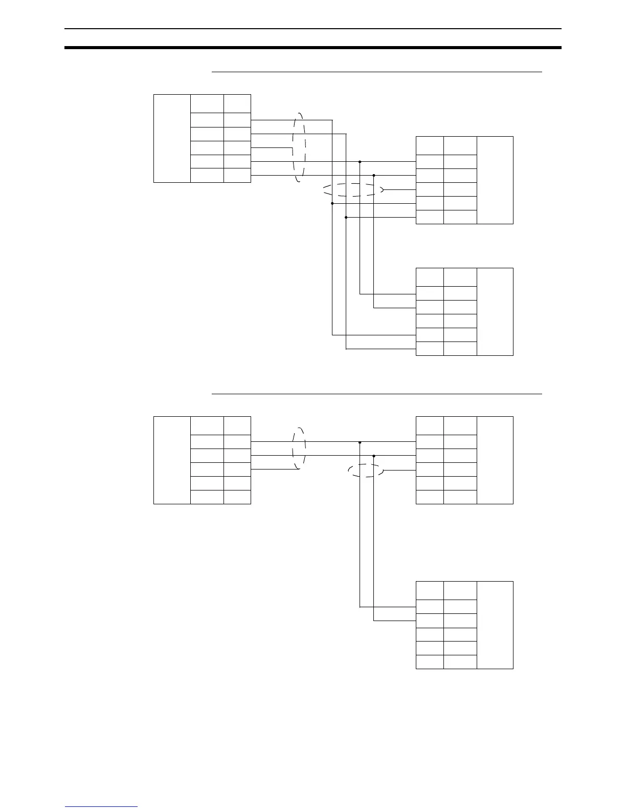
1:N, 4-wire Connections Using RS-422A/485 Port 2 (MCW151-E only)
Note MC Unit Communication Modes: Host Link Master and Slave
1:N, 2-wire Connections Using RS-422A/485 Port 2 (MCW151-E only)
Note 1. MC Unit Communication Mode: General-purpose
2. For the 2-wire system (Switch SW2: pin 1,2 =ON), the RD- and SD- resp.
the RD+ and SD+ are interconnected within the MC Unit.
MC Unit
RS-422A
Interface
Signal Pin
RD- 1
RD+ 2
FG 3
SD- 4
SD+ 5
MC Unit
Pin Signal
RS-422A
Interface
1 RD-
2 RD+
3FG
4SD-
5SD+
MC Unit
Pin Signal
RS-422A
Interface
1 RD-
2 RD+
3FG
4SD-
5SD+
COMBICON
Plug
COMBICON
Plug
COMBICON
Plug
DIP switch SW2
Pin 1 OFF
Pin 2 OFF
Pin 3 ON
DIP switch SW2
Pin 1 OFF
Pin 2 OFF
Pin 3 OFF
DIP switch SW2
Pin 1 OFF
Pin 2 OFF
Pin 3 ON
MC Unit
RS-485
Interface
Signal Pin
RD- 1
RD+ 2
FG 3
SD- 4
SD+ 5
MC Unit
Pin Signal
RS-485
Interface
1 RD-
2 RD+
3FG
4SD-
5SD+
MC Unit
Pin Signal
RS-485
Interface
1 RD-
2 RD+
3FG
4SD-
5SD+
COMBICON
Plug
COMBICON
Plug
COMBICON
Plug
DIP switch SW2
Pin 1 ON
Pin 2 ON
Pin 3 ON
DIP switch SW2
Pin 1 ON
Pin 2 ON
Pin 3 OFF
DIP switch SW2
Pin 1 ON
Pin 2 ON
Pin 3 ON