38
Wiring Section 2-3
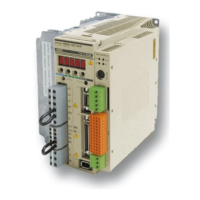
Encoder Output
2-3-5 Connection examples
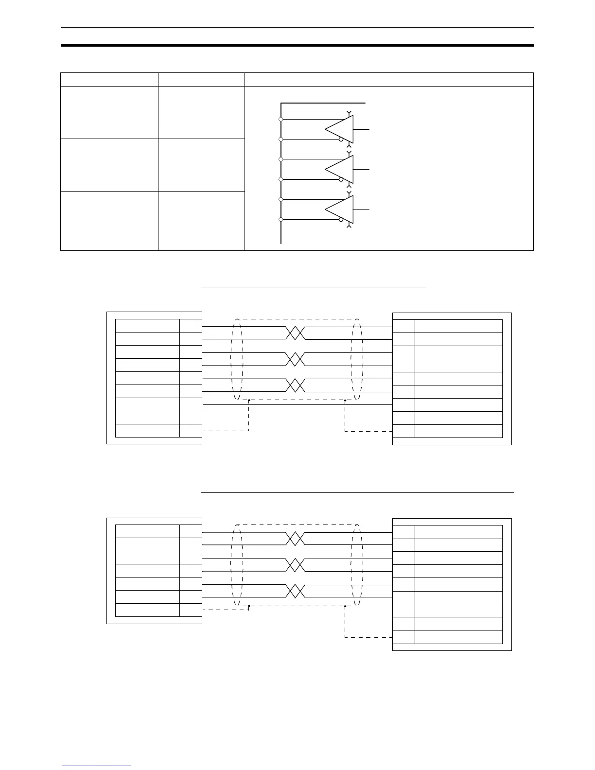
Cascading encoder signal (MCW151 to MCW151)
Connecting master encoder input signal from W-series Servo Driver
Item Specification Circuit Configuration
Signal level EIA RS-422A Stan-
dards
Maximum frequency 500 kp/s
Galvanic isolation No
A+
2
A-
1
Motion Control Unit
Phase A axis 1
4
B-
3
Phase B axis 1
B+
6
Z-
5
Phase Z axis 1
Z+
Line transmitter
0V
+5V
0V
+5V
0V
+5V
MCW151 (output)
A+ 1
A- 2
B+ 3
B- 4
Z+ 5
Z- 6
0V_ENC 7
5V_ENC 8
FG 10
MCW151 (input)
1A+
2A-
3B+
4B-
5Z+
6Z-
7 0V_ENC
8 5V_ENC
10 FG
W-series Servo Driver
A+ 33
A- 34
B+ 36
B- 35
Z+ 19
Z- 20
FG
Shell
MCW151 (input)
1A+
2A-
3B+
4B-
5Z+
6Z-
7 0V_ENC
8 5V_ENC
10 FG