37
Wiring Section 2-3
Digital Outputs
Output response times
The response times given in the following table are the times between a
change in the OP parameter and the corresponding change in the digital out-
put circuit.
These times are mainly depending on the MC Unit’s Servo Period and they
include the physical delays in the output circuit.
Encoder Input
Description Delay Time
Digital Input I0/R0 and I1/R1 (rising edge) 50 s
Digital Input I0/R0 and I1/R1 (falling edge) 150 s
Z-marker (rising edge) 2 s
Z-marker (falling edge) 2 s
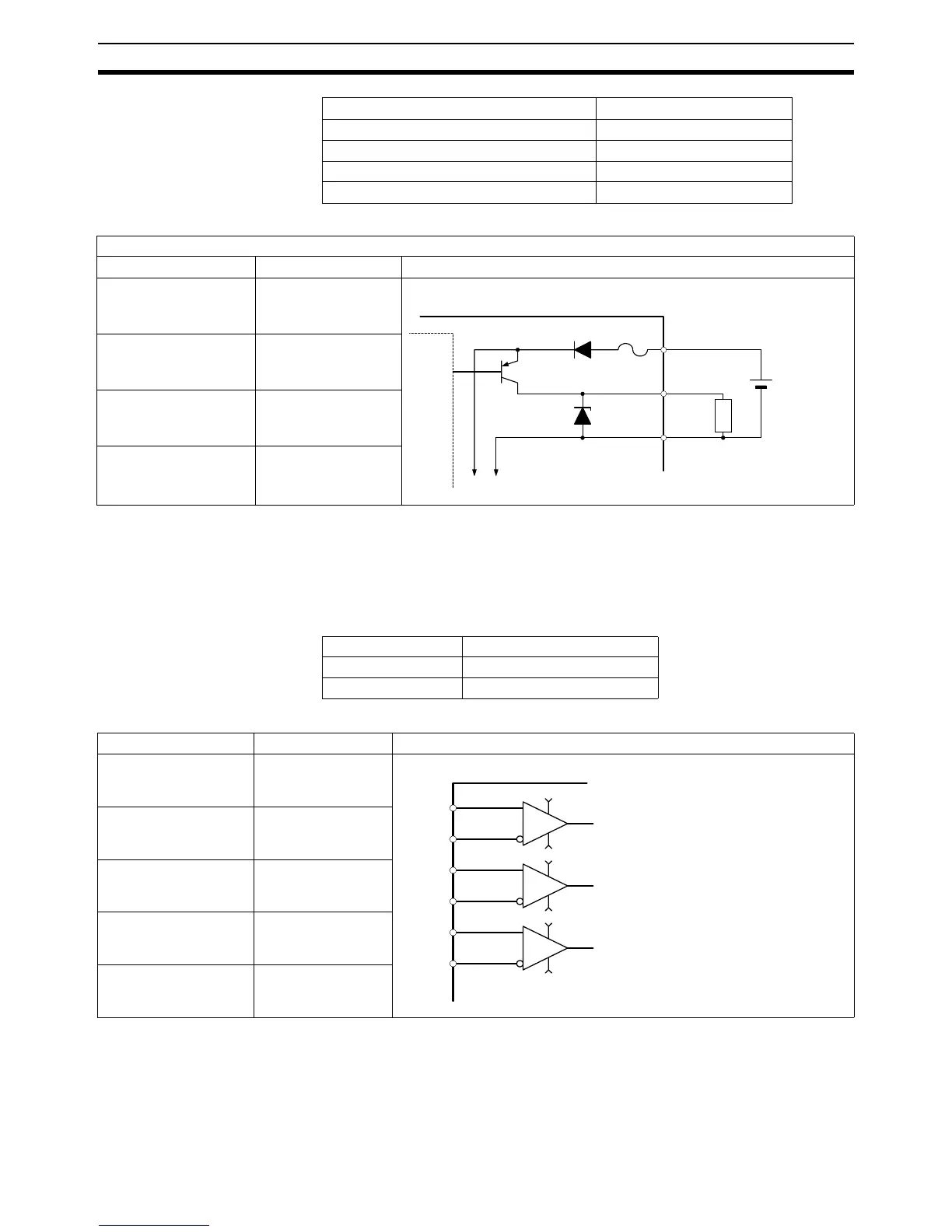
Digital outputs: O8 to O13
Item Specification Circuit Configuration
Ty pe PN P
Current capacity 100 mA each output
(600 mA total for
group of 6)
Maximum voltage 24 V + 10%
Protection Over current, over
temperature and 2 A
fuse on common
To other output circuits
Internal Circuitry (galvanically
isolated from system)
Motion Control Unit
0V_OP
24V_OP
O8
2A Fuse
19
26
25
External power
supply 24V
LOAD
Equivalent
circuit
Servo Period Response time
0.5 ms 0.8 ms (max.)
1.0 ms 1.3 ms (max.)
Item Specification Circuit Configuration
Signal level EIA RS-422A Stan-
dards
Input impedance 48 k min.
Response frequency 1500 kp/s
Termination Yes, 220 select-
able by switch
Galvanic isolation No
Motion Control Unit
Phase A axis 1
Phase B axis 1
Phase Z axis 1
Line receiver
0V
+5V
0V
+5V
0V
+5V
A+
2
A-
1
4
B-
3
B+
6
Z-
5
Z+
Ω
Ω