4-15
4-2 Wiring
OMNUC G5-Series AC Servo Drives Users Manual (Built-in MECHATROLINK-II communications type)
4
System Design
R88D-KN30H-ML2/-KN50H-ML2
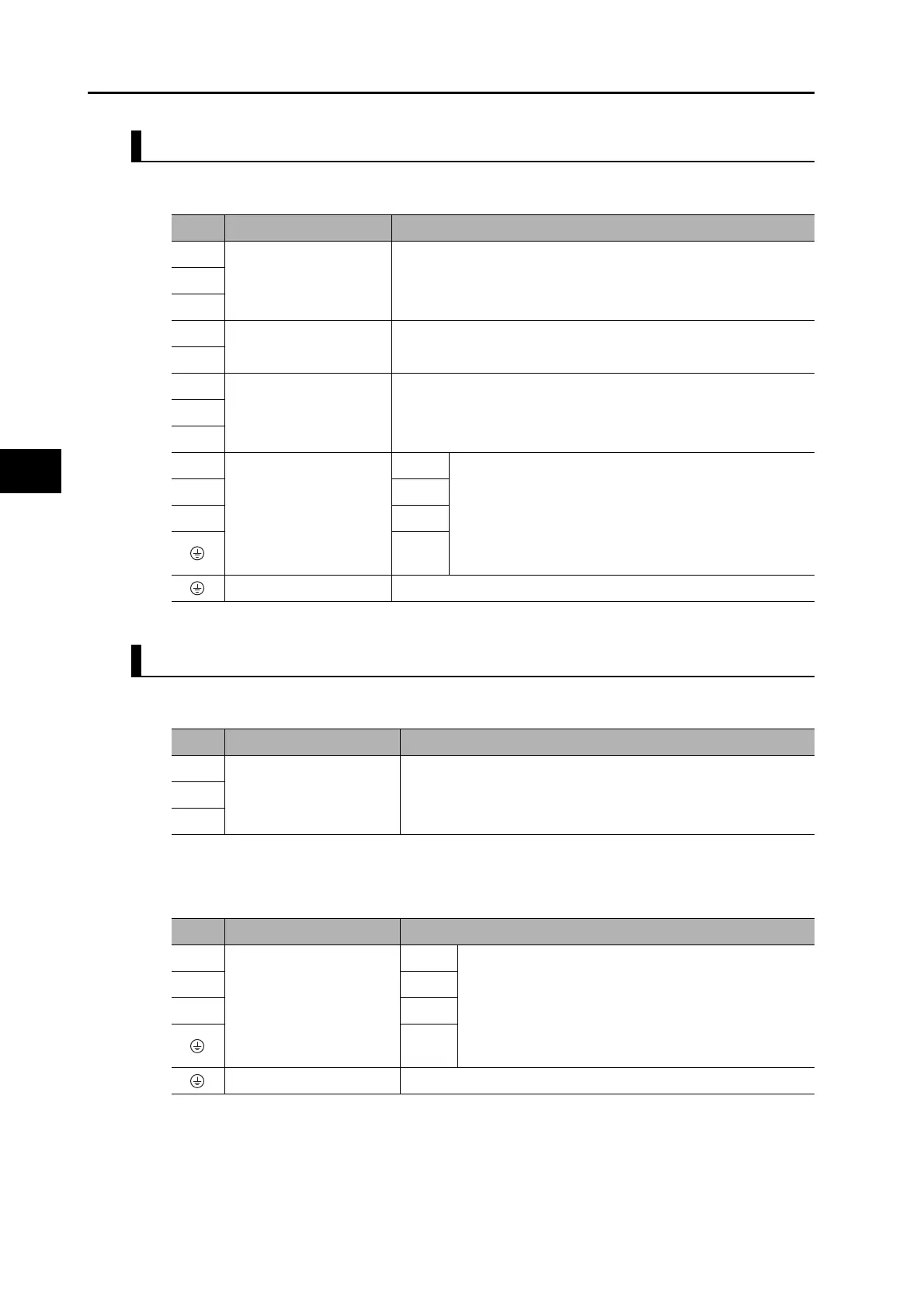
Terminal Block Specifications
R88D-KN06F-ML2/-KN10F-ML2/-KN15F-ML2/-KN20F-ML2
Main Circuit Connector Specifications (CNA)
Motor Connector Specifications (CNB)
Symbol
Name Function
L1
Main circuit power supply
input
R88D-KNxH-ML2 (3 to 5 kW): 3-phase 200 to 230 VAC (170 to 253
V) 50/60 Hz
L2
L3
L1C
Control circuit power
supply input
R88D-KNxH-ML2: Single-phase 200 to 230 VAC (170 to 253 V) 50/
60 Hz
L2C
B1
External Regeneration
Resistor connection
terminals
Normally B2 and B3 are connected. Do not short B1 and B2. Doing
so may cause malfunctions. If there is high regenerative energy,
remove the short-circuit bar between B2 and B3 and connect an
External Regeneration Resistor between B1 and B2.
B2
B3
U
Motor connection
terminals
Red These are the output terminals to the Servomotor.
Be sure to wire them correctly.
VWhite
WBlue
Green/
Yellow
Frame ground This is the ground terminal. Ground to 100 or less.
Symbol
Name Function
L1 Main circuit power supply
input
R88D-KNxF-ML2
(600 W to 2 kW) : 3-phase: 380 to 480 VAC (323 to 528 V) 50/60
Hz
L2
L3
Symbol
Name Function
U Motor connection
terminals
Red These are the output terminals to the Servomotor.
Be sure to wire them correctly.
VWhite
WBlue
Green/
Yellow
Frame ground This is the ground terminal. Ground to 10 or less.

 Loading...