6
6-38
6-10 Gain Switching 3 Function
OMNUC G5-Series AC Servo Drives Users Manual (Built-in MECHATROLINK-II communications type)
Applied Functions
Operation Example
When the conventional gain switching function works correctly, set a time to use the Gain 3
into the Gain 3 Effective Time (Pn605), and the magnification of Gain 3 against Gain 1 into the
Gain 3 Ratio Setting (Pn606).
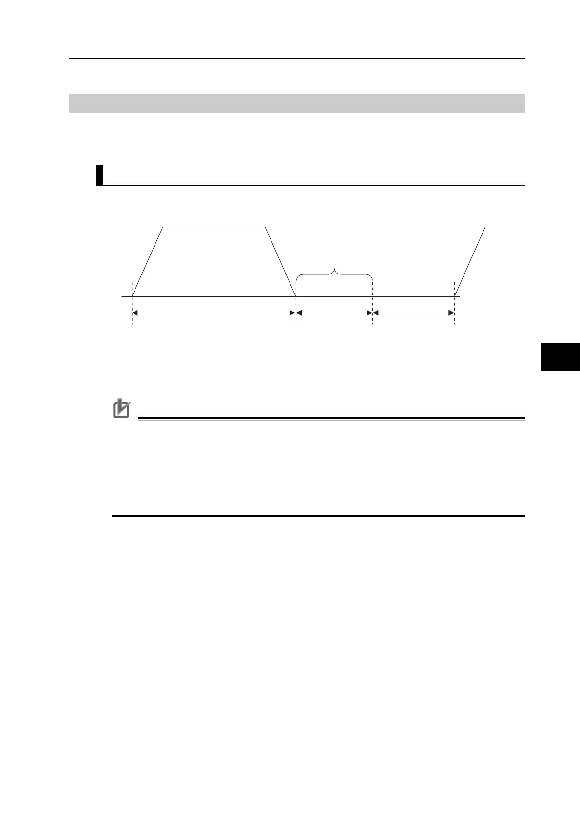
Operation Timings of Gain 1, 2 and 3
When the SWITCHING mode in Position Control (Pn115) is set to 7, i.e., when the command
pulses are received as the switching condition, the operation will be as shown below:
Precautions for Correct Use
If gain 3 is not used, set the Gain 3 Effective Time (Pn605) to 0 and Gain 3 Ratio Setting (Pn606) to 100.
In the gain 3 region, only the position loop gain and the speed loop gain are treated as gain 3, and
the gain 1 setting is applied to all other gains.
If the gain 2 switching condition is established in the gain 3 region, this switches to gain 2.
If gain 2 is switching to gain 3, Position Gain Switching Time (Pn119) is enabled.
Take note that there is a gain 3 region even when gain 2 is switched to gain 1 due to a parameter
change and so forth.
Gain 2
Gain 3
Gain 1
Position command speed [r/min]
Pn605×0.1ms
Pn105 to Pn109
Gain 3 region
Position loop gain=Pn100×Pn606/100
Speed loop gain=Pn101×Pn606/100
Continue to use gain 1 value for the speed loop integral time constant,
speed feedback filter time constant, and torque command filter time constant.
Pn100 to Pn104
 Loading...
