6-1
6-1 Sequence I/O Signal
OMNUC G5-Series AC Servo Drives Users Manual (Built-in MECHATROLINK-II communications type)
6
Applied Functions
6-1 Sequence I/O Signal
You can set a sequence in various operating conditions.
For the connection of I/O signals and processing of external signals, refer to "Control I/O
Connector Specifications (CN1)" (P.3-13).
Input Signals
You can allocate any function of input signals to the input pins for the control I/O connector
(CN1). In addition, you can change logics. However, refer to "Input Signal Allocation Method"
(P.6-2) for more information because some signals have an allocation limit.
If the G Series is being replaced, set the unit to the default setting before using it.
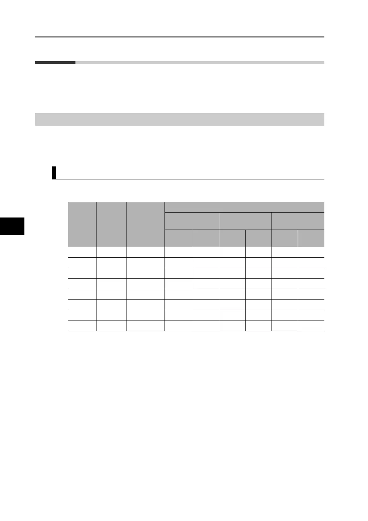
Input Signal Default Setting
The allocation of the default input signals is as follows. Refer to "Input Signal Allocation
Method" (P.6-2) when you change the allocation to use.
*1. NO (normally open) contact and NC (normally close) contact in the table above refer to the
following states.
NO: Disabled (OFF) when signal input is open with COM
Enabled (ON) when signal input is shorted with COM
NC: Disabled (OFF) when signal input is shorted with COM
Enabled (ON) when signal input is open with COM
"" indicates the status where no function is allocated.
Applicable
parameters
Input
signals
Factory
default
setting (hex)
Default setting state
Position control or
full closing control
Speed control Torque control
Signal
name
Logic
*1
Signal
name
Logic
*1
Signal
name
Logic
*1
Pn400 IN1 00949494h STOP
NC
STOP
NC
STOP
NC
Pn401 IN2 00818181h POT
NC
POT
NC
POT
NC
Pn402 IN3 00828282h NOT
NC
NOT
NC
NOT
NC
Pn403 IN4 00222222h DEC
NO
DEC
NO
DEC
NO
Pn404 IN5 002B2B2Bh EXT3
NO
EXT3
NO
EXT3
NO
Pn405 IN6 00212121h EXT2
NO
EXT2
NO
EXT2
NO
Pn406 IN7 00202020h EXT1
NO
EXT1
NO
EXT1
NO
Pn407 IN8 002E2E2Eh MON0
NO
MON0
NO
MON0
NO

 Loading...