8-11
8-2 Gain Parameters
OMNUC G5-Series AC Servo Drives Users Manual (Built-in MECHATROLINK-II communications type)
8
Parameters Details
Select the conditions for switching between gain 1 and gain 2 when the GAIN SWITCHING INPUT
OPERATING mode Selection (Pn114) is set to 1.
The gain is always gain 1 regardless of the gain input if the SWITCHING mode in Position Control
(Pn115) is 2 and the Torque Limit Selection (Pn521) is 3 or 6.
Explanation of Settings
*1. The Gain Switching Delay Time in Position Control (Pn116) becomes effective when the gain is
switched from 2 to 1.
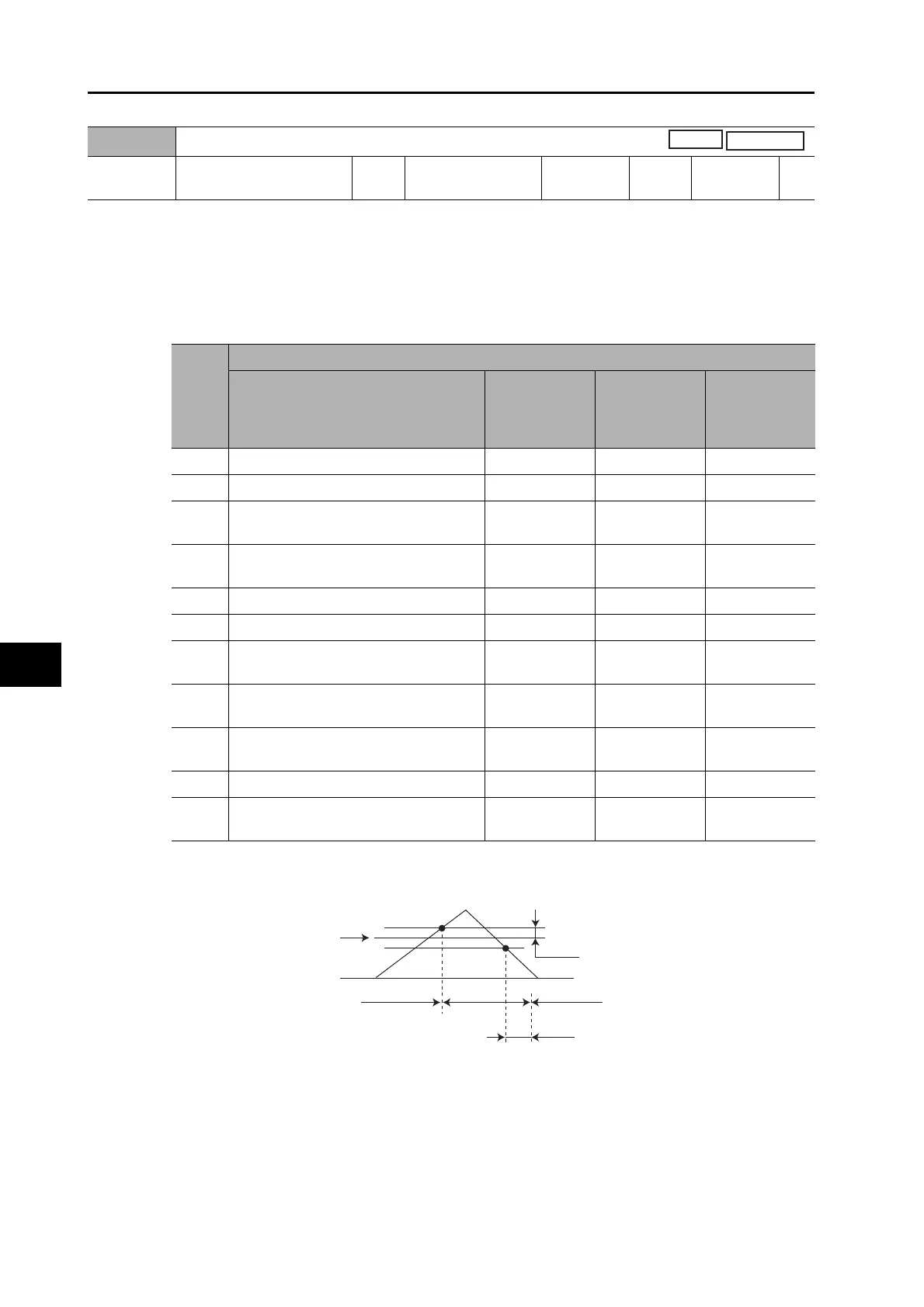
*2. The Gain Switching Hysteresis in Position Control (Pn118) is defined in the drawing below.
*3. When the Gain switching command of MECHATROLINK-II communications is 0, the gain switches to
1. When the command is 1, the gain switches to 2.
*4. The variation means the change amount in a millisecond (ms).
E.g. The set value is 200 when the condition is a 10% change in torque in 1 millisecond.
*5. The unit (pulse) of hysteresis is the resolution of the encoder in position control. It is the resolution of
the external encoder in full closing control.
Pn115
SWITCHING mode in Position Control
Setting
range
0 to 10 Unit
Default
setting
0
Data
attribute
B
Pn115
set
value
Description
Gain switching conditions
Gain switching
delay time in
position control
(Pn116)
*1
Gain switching
level in position
control (Pn117)
Gain switching
hysteresis in
position control
(Pn118)
*2
0 Always Gain 1 (Pn100 to Pn104). Disabled Disabled Disabled
1 Always Gain 2 (Pn105 to Pn109). Disabled Disabled Disabled
2
Gain switching command input via
MECHATROLINK-II communications
*3
Disabled Disabled Disabled
3
Torque command variation (Refer to
Figure A)
Enabled
Enabled
*4
(0.05%)
Enabled
*4
(0.05%)
4 Always Gain 1 (Pn100 to 104). Disabled Disabled Disabled
5 Command speed (Refer to Figure B) Enabled Enabled (r/min) Enabled(r/min)
6
Amount of position error (Refer to
Figure C).
Enabled
Enabled
*5
(pulse)
Enabled
*5
(pulse)
7
When the position command is entered
(Refer to Figure D).
Enabled Disabled Disabled
8
When the positioning complete signal
(INP) is OFF (Refer to Figure E).
Enabled Disabled Disabled
9 Actual motor speed (Refer to Figure B). Enabled Enabled (r/min) Enabled (r/min)
10
Combination of position command input
and rotation speed (Refer to Figure F).
Enabled
Enabled
*6
(r/min)
Enabled
*6
(r/min)
Pn117
0
Pn118
Pn116
Gain 1
Gain 2
Gain 1

 Loading...