8-40
8-5 Interface Monitor Setting Parameters
OMNUC G5-Series AC Servo Drives Users Manual (Built-in MECHATROLINK-II communications type)
8
Parameters Details
Select the warning type to be output by the Warning Output 1.
Refer to "11-2 Warning (P.11-4)".
Explanation of Set Values
Select the warning type to be output by the Warning Output 2.
Refer to the Warning Output 1 (Pn440) for the parameter setting method.
Refer to "11-2 Warning (P.11-4)".
Set the positioning completion range to output the Positioning completion output 2 (INP2).
The positioning completion output 2 (INP2) is always ON when the position error is below the set
value, regardless of the setting on the Positioning Completion Condition Selection (Pn432).
The positioning completion output 2 (INP2) does not involve determination by the position
commands. It is ON as long as the position error is below the set value.
The setting unit is command. It can be changed to encoder unit by the Position Setting Unit
Selection (Pn520). However, note that unit for error counter overflow level change as well.
Refer to the Positioning Completion Range 1 (Pn431) for the parameter setting method.
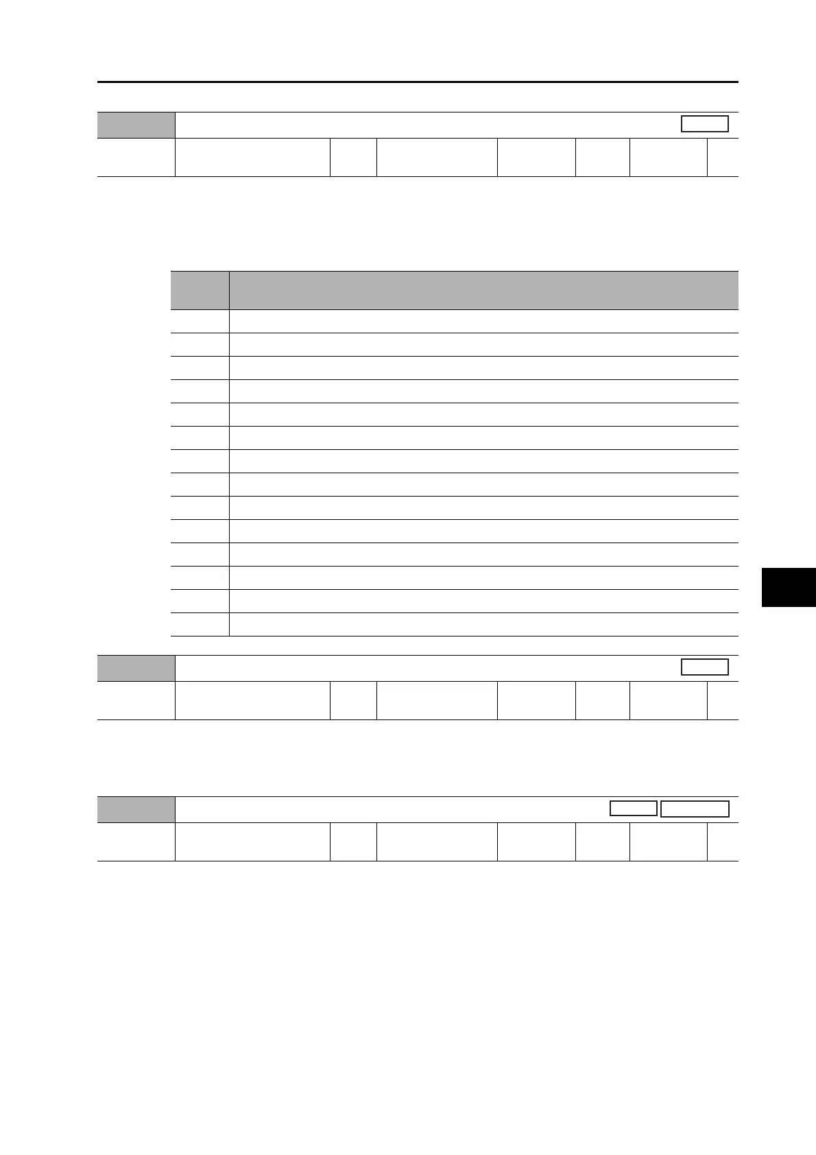
Pn440
Warning Output Selection 1
Setting
range
0 to 13 Unit
Default
setting
0
Data
attribute
A
Set
value
Description
0 Output by all types of warnings
1 Overload warning
2 Excessive regeneration warning
3 Battery warning
4Fan warning
5 Encoder communications warning
6 Encoder communications warning
7 Vibration warning
8 Service life warning
9 External encoder error warning
10 External encoder communications error warning
11 Data setting warning
12 Command warning
13 MECHATROLINK-II communications warning
Pn441
Warning Output Selection 2
Setting
range
0 to 13 Unit
Default
setting
0
Data
attribute
A
Pn442
Positioning Completion Range 2
Setting
range
0 to 262144 Unit Command unit
Default
setting
10
Data
attribute
A
Position
Full closing

 Loading...