9-3
9-2 Preparing for Operation
OMNUC G5-Series AC Servo Drives Users Manual (Built-in MECHATROLINK-II communications type)
9
Operation
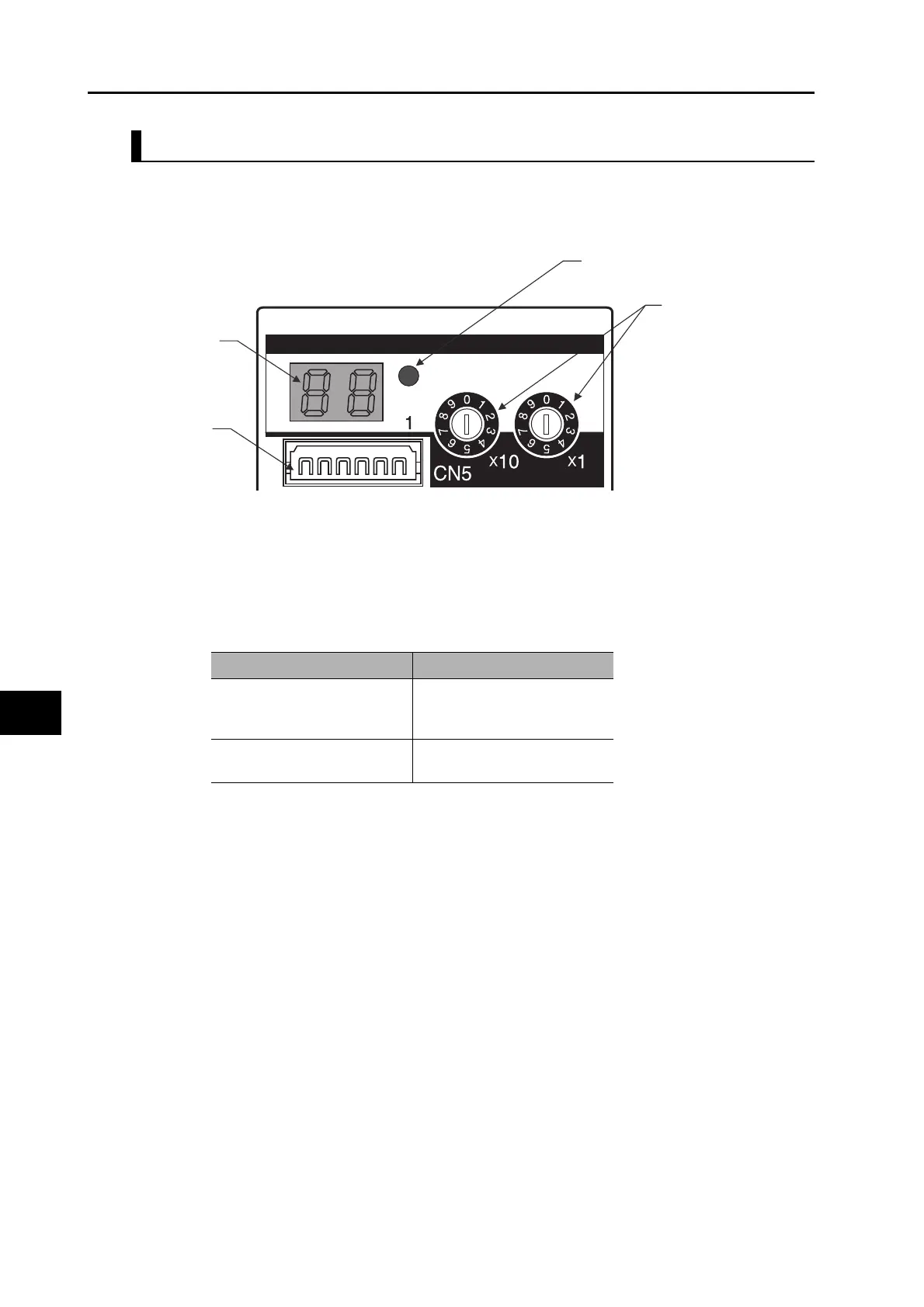
Display Area and Setting on Drives
This is the display area of R88D-KNx Servo Drive.
There are the rotary switches to set the MECHATROLINK-II communication node address, the
Drive alarm indicator, and the MECHATROLINK-II communications status LED indicator.
Note 1. The node address set by the rotary switch is read only once when the control power is turned on.
Any changes made by the rotary switches after the power-on are not reflected to the Controller.
Such changes become effective only after the subsequent power-on following to a power-off.
Do not change the rotary switch setting after the power-on.
Note 2. The settable range for a node address is between 1 and 31. The node address used over the
network is the value obtained by adding the offset 40h to the rotary switch set value.
If any value over or under the range is set, the Node address setting error (Alarm No.82.0) occurs.
MECHATROLINK-II communications
status LED indicator (COMM)
Rotary switches for
node address setting
Connector for
Analog Monitor
7-segment LED
indicator (2-digit)
ADR
COMM
Rotary switch setting Description
1 to 31
Node address = Set value +
40h (41h Node address
5Fh)
Others
Node address setting error
(Alarm No.82.0) occurs.

 Loading...