7-14
D Response
Normal
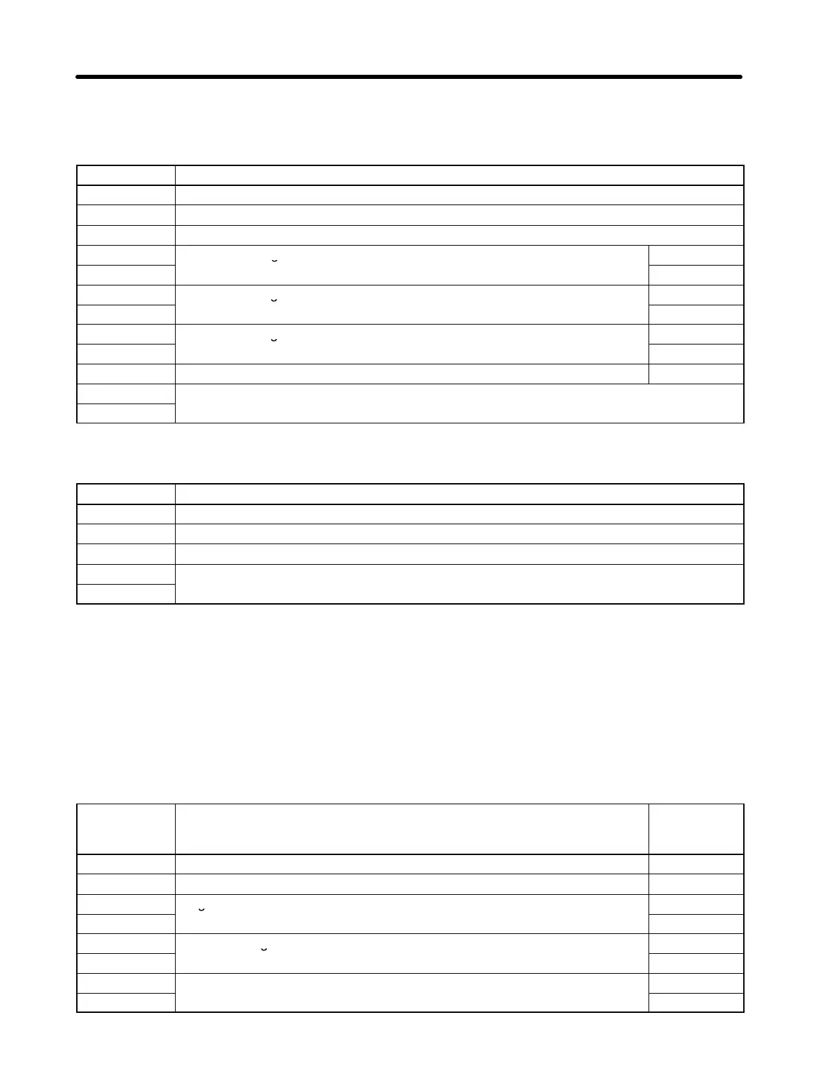
Byte No. Data
1 Slave address
2 Function code (03 Hex)
3 Number of bytes of attached data
4
Data of start register
MS B
5
LSB
6
Data of next register
MSB
7
LSB
8
Data of next register
MSB
9
LSB
: : :
n–1
CRC-16 check
n
Error
Byte No. Data
1 Slave address
2 Function code (83 Hex)
3 Error code
4
CRC-16 check
5
Note When an error occurs, the MSB of the function code will be set to 1.
H Example of Data Read
• In the following example, four-register data (status signal data) is read from register 0020 Hex of the
Inverter with a Slave address of 02.
D DSR Message
Byte No. Data Data
example
(Hex)
1 Slave address 02
2 Function code 03
3
Register No. of read start data
00
4
20
5
Number of registers of read data
00
6
04
7
CRC-16 check
45
8 F0
Communications Chapter 7