3-11
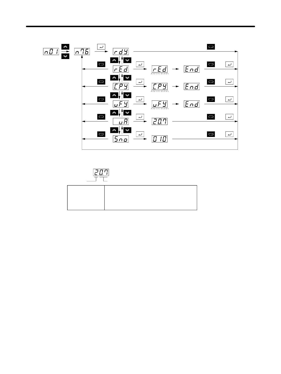
H Display Transitions
Reading
Writing
Verifying
Inverter capacity
Software No.
Reading
completed
Writing
completed
or
or
Verifying
completed
or
or
or
Note The following table shows the display for the Inverter capacity (vA).
Voltage class
Maximum applicable Servomotor capacity
2: Three-phase 200 V
b: Single-phase 200 V
4: Three-phase 400 V
0.1: 0.1 kW (0.1 kW)
0.2: 0.2 kW (0.25 kW/0.37 kW)
0.4: 0.4 kW (0.55 kW)
0.7: 0.75 kW (1.1 kW)
1.5: 1.5 kW (1.5 kW)
2.2: 2.2 kW (2.2 kW)
3.7: 3.7 kW (3.7 kW)
Note The figures in parentheses indicate typical motor capacities in Japan.
3-2-2 Procedure for Copying Parameters
• Use the following procedure to copy parameters to another Inverter.
1. Set the Parameter Write-prohibit Selection/Parameter Initialization (n01) to 1.
2. Set the Parameter Read Prohibit Selection (n77) to 1 to enable reading.
3. Read the Inverter parameter settings to the Digital Operator memory (rEd).
4. Turn OFF the Inverter power supply, and remove the Digital Operator.
5. Install the Digital Operator on the Inverter you want to copy to, and then turn ON the power supply.
6. Copy the contents of the memory in the Digital Operator to the Inverter (CPy).
7. Verify and check that writing was performed correctly (vFy).
• Parameters can be copied only between Inverters that have the same power supply specifications
and control mode (i.e., V/f control or vector control). For example, copying cannot be performed from a
200-V-class Inverter to a 400-V-class Inverter or from a V/f-control-mode Inverter to a vector-control-
mode Inverter.
Note The saved hold output frequency and the following parameters will not be copied.
Preparing for Operation and Monitoring Chapter 3