7-29
7-9 Self-diagnostic Test
The Inverter incorporates a self-diagnostic test function that checks whether
RS-422/485 communications are functioning.
If the Inverter has a communications failure, take the steps provided below to check
whether the communications function of the Inverter is normal.
H Self-diagnostic Test Steps
1. Set the Parameter
S Set n39 for multi-function input 4 (S5) to 35 through the Digital Operator.
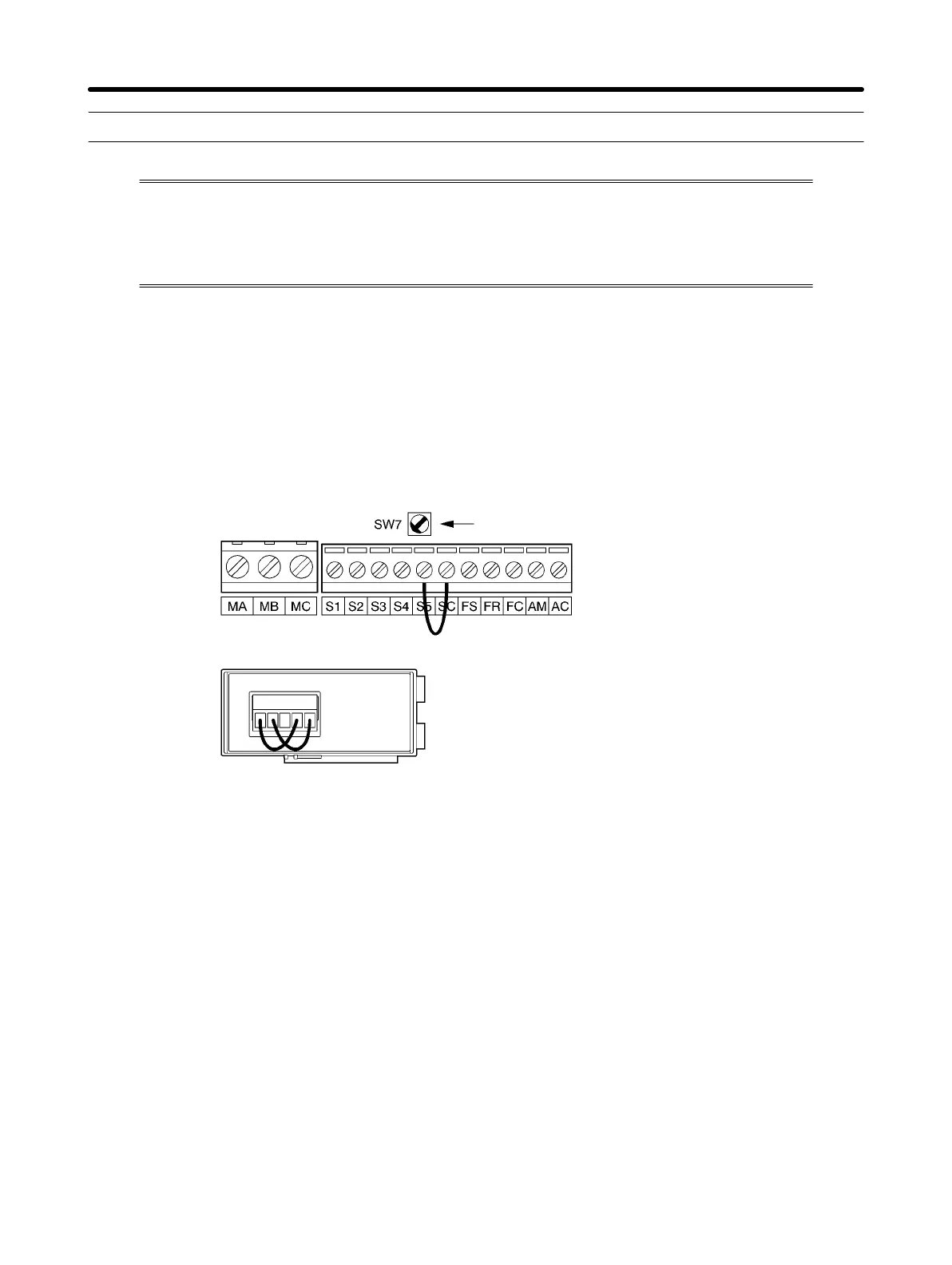
2. Turn OFF the Inverter and Wire the Terminal
S Turn OFF the Inverter and wire the following control terminals. At this time, make sure that all other
circuit terminals are open.
Set SW7 to NPN.
Connect S5 and SC.
Connect R+ and S+.
Connect R– and S–.
3. Turn ON the Inverter and Check the Display
S Turn ON the Inverter.
S Check the display on the Digital Operator.
Normal
The display is normal with no error code displayed.
Fault
The display shows “CE” (communications time-over) or “CAL” (communications standby). In
either case, the communications circuit of the Inverter is broken. Replace the Inverter.
Communications Chapter 7