2-17
H Wiring on the Input Side of the Main Circuit
D Installing a Molded-case Circuit Breaker
Always connect the power input terminals (R/L1, S/L2, and T/L3) and power supply via a molded case
circuit breaker (MCCB) suitable to the Inverter.
• Install one MCCB for every Inverter used.
• Choose an appropriate MCCB capacity according to the Circuit breaker capacity column in the table
on the previous page.
• For the MCCB’s time characteristics, be sure to consider the Inverter’s overload protection (one min-
ute at 150% of the rated output current).
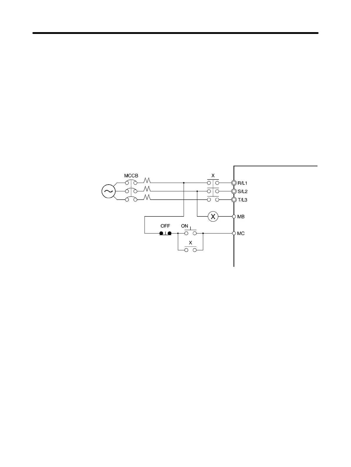
• If the MCCB is to be used in common among multiple Inverters, or other devices, set up a sequence
such that the power supply will be turned off by a fault output, as shown in the following diagram.
3-phase/Single-phase
200 V AC
3-phase 400 V AC
Power
supply
Inverter
Fault output
(NC)
D Installing a Ground Fault Interrupter
Inverter outputs use high-speed switching, so high-frequency leakage current is generated.
In general, a leakage current of approximately 100 mA will occur for each Inverter (when the power
cable is 1 m) and approximately 5 mA for each additional meter of power cable.
Therefore, at the power supply input area, use a special-purpose breaker for Inverters, which detects
only the leakage current in the frequency range that is hazardous to humans and excludes high-fre-
quency leakage current.
• For the special-purpose breaker for Inverters, choose a ground fault interrupter with a sensitivity am-
perage of at least 10 mA per Inverter.
• When using a general leakage breaker, choose a ground fault interrupter with a sensitivity amperage
of 200 mA or more per Inverter and with an operating time of 0.1 s or more.
D Installing a Magnetic Contactor
If the power supply of the main circuit is to be shut off because of the sequence, a magnetic contactor
can be used instead of a molded-case circuit breaker.
When a magnetic contactor is installed on the primary side of the main circuit to stop a load forcibly,
however, the regenerative braking does not work and the load coasts to a stop.
Design Chapter 2