EasyManua.ls Logo

OPHIR BeamSquared User Manual

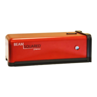
OPHIR BeamSquared
112 pages
To Next Page IconTo Next Page
Page #1 background imageLoading...
Page #1 background image
BeamSquared
®
User Guide
Beam Propagation Analyzer
For Windows 7
®
and Window 10
®
64 BIT
For Sales, Service or Technical Support
Phone: (435) 753-3729
Fax: (435) 753-5231
Service Email
service@us.ophiropt.com
Sales Email
sales@us.ophiropt.com
Ophir-Spiricon, LLC
3050 North 300 West
North Logan, Utah 84341
©2019 Ophir-Spiricon, LLC

Table of Contents

Questions and Answers:

OPHIR BeamSquared Specifications

General IconGeneral
Weight300 g
Beam Diameter RangeFew microns to 9 mm
Resolution0.1 μm
InterfaceUSB
Operating Temperature10-35 °C
Storage Temperature-20-60 °C

Summary

Chapter 1 General Information

1.1 Safety

Essential safety precautions for operating the BeamSquared system and handling lasers.

1.2 BeamSquared Model Numbers

Details on different BeamSquared hardware models and their part numbers.

1.3 Specifications

Technical specifications including environmental, power, physical, and optical data.

1.4 BeamSquared Optical Train Dimensions

Diagrams illustrating the physical dimensions of the BeamSquared optical train.

1.5 Software Information

Overview of software capabilities, compatibility, and required equipment.

Chapter 2 Setup

2.1 Equipment

Lists the components included in the BeamSquared system package.

2.2 BeamSquared Software Installation

Step-by-step guide for installing the BeamSquared software on a PC.

2.3 Prepare the BeamSquared for Operation

Instructions for physically setting up the BeamSquared hardware, including mounting and connecting.

2.4 External Attenuation of the Beam

Guidance on using attenuation to protect the camera and ensure measurement accuracy.

2.5 Beam Alignment and Setup for Auto Mode

Procedures for aligning the laser beam with the BeamSquared optical path for automatic measurements.

2.6 Step Size and Start/Stop Selection

Configuration of measurement parameters for data acquisition runs, including step size and range.

Chapter 3 Operating Controls and User Interface

3.1 User Interface

Overview of graphical interface elements like title bars, ribbons, and status bars.

3.2 Application Tools

Tools for file access, data export, and interface customization.

3.3 Run Ribbon

Controls for initiating, configuring, and managing measurement runs.

3.4 Table Ribbon

Controls for managing the optical train's Z-axis positioning and attenuation.

3.5 Source Ribbon

Camera-specific controls for exposure, gamma, and trigger settings.

3.6 Data Ribbon

Controls for data logging, report generation, and data export.

3.7 Views Ribbon

Options for displaying measurement results and data visualizations.

3.8 Interface Customization

Features for personalizing the display environment through docking and layout options.

Chapter 4 Operation

4.1 Operating Modes

Description of different measurement modes like Automated Stepping, ISO Setup, and Four Cuts.

4.2 BeamSquared Operation

Detailed steps for configuring and performing measurements using the software.

4.3 Data Collection in Auto Mode

Process of collecting frames and data points during an automated measurement run.

4.4 Useful Operations and Functions

Description of less obvious but helpful features like Z Locations and curve fitting.

Chapter 5 M2 Tutorial and Theory

5.1 Introduction to M2

Explanation of the M2 beam quality metric and its significance.

5.2 M2 < 1

Discussion on M2 results less than one and potential causes.

5.3 Laser Beam Parameters

Definition of key parameters predicting beam propagation like waist width and divergence.

5.4 An M2 Tutorial

Practical guide to understanding beam propagation using a focusing lens.

5.4.1 The Transforming Lens

Explanation of how a focusing lens transforms the input beam for measurement.

5.4.2 Beam Width Measurement Criteria

Standards and methods used for accurate beam width measurements.

5.4.3 Spot Size and Resolution

Operational limits and considerations related to spot size and camera resolution.

5.4.4 Attenuation and Distortions

Importance of attenuation and potential beam distortions introduced by optical elements.

5.5 M2 Theory of Operation

Detailed explanation of how BeamSquared measures M2 using its system components.

5.6 Operation Limitations

Factors limiting measurement accuracy, including aberrations and beam stability.

5.7 Electro-Mechanical Operation

How the system's mirrors and camera movement facilitate data collection.

5.8 Data Collection

Guidelines for collecting data points to ensure accurate propagation parameter calculation.

Chapter 6 M2 Computations

6.1 Curve Fitting

Methodology for fitting data points to propagation equations using non-linear least squares.

6.1.1 M2, K Factor, and BPP

Formulas for calculating beam quality metrics M2, K Factor, and BPP.

6.1.2 Translation Equations

Equations used to translate measured parameters into real laser beam characteristics.

6.1.2.2 Waist Width

Explanation of beam width calculation methods and their implications.

6.1.2.3 Waist Location

Methods for determining waist location relative to the principal plane or laser aperture.

6.1.3 Rayleigh Range

Calculation and significance of the Rayleigh range for beam collimation.

6.1.4 Astigmatism and Asymmetry

Ancillary values indicating beam shape deviations and circularity.

6.1.5 Focal Length Calculation

Procedure for calculating wavelength-adjusted focal lengths for lenses.

6.1.6 Path Length Calibration Values

Definition and usage of factory-calibrated path length values for system calibration.

6.1.7 BeamSquared Distance

Application of thin lens equations for determining laser placement relative to the lens.

Chapter 7 Troubleshooting

7.1 Setup and Startup Problems

Common issues encountered during system setup and initial startup.

7.2 Operation Problems

Solutions for problems that occur during normal measurement operation.

Chapter 8 BeamSquared Automation Interface

8.1 Evolution of the Automation Interface

History and technical basis of the BeamSquared automation interface.

8.2 Recommended Skill Set

Guidance on the skills required for developing automation clients.

8.3 Documentation

Information on accessing the Automation API reference and documentation.

8.4 Examples

Location and access methods for sample automation applications.

Chapter 9 Manual M2 Measurements

9.1 Electro-Mechanical Operation

Setup and operation specific to Manual Mode, requiring manual system control.

9.2 Spot Size Resolution

Considerations for spot size and resolution in relation to focused waist location.

9.3 Manual Mode

Procedures for setting up and performing measurements in Manual Mode.

9.3.1 Optical Rail Setup

Steps for configuring the optical rail, lens, and beam alignment for manual operation.

9.3.2 Beam Alignment and Setup for Manual Mode

Detailed steps for aligning the beam and setting up the camera for manual measurements.

9.3.3 Adjusting Beam Alignment

Guidance on adjusting beam intensity and alignment for optimal manual measurements.

9.3.4 Step by Step Wizard

Using the wizard to collect data at specified positions in Manual Mode.

9.3.5 Exposure

Setting the camera exposure time for manual measurements to optimize image quality.

Appendix A Lens Calibration Adjustments

A.1 Plano convex Lens Calibration

Formula and procedure for correcting focal length for different wavelengths.

A.2 Refractive Index of Common Lens Materials

Table of refractive index values for common lens materials at various wavelengths.

Appendix B Warranty

Appendix C BeamSquared Supported Cameras

Appendix D Camera Information

D.1 SP300

Technical details, accessories, and connector descriptions for the SP300 camera.

D.2 SP920

Technical details, accessories, and connector descriptions for the SP920 camera.

D.3 XEVA XC-130

Installation, setup, and operation details for the XEVA XC-130 camera.

D.3.2 Getting Started with Xeva XC-130 camera

Initial setup steps for connecting and configuring the XEVA XC-130 camera.

D.3.3 XenICs XEVA XC-130 Camera Operation

Specific camera controls and features for the XEVA XC-130, including exposure and correction files.

D.3.3.3 Temperature

Information on the camera's thermoelectric cooler and temperature stabilization.

Related product manuals