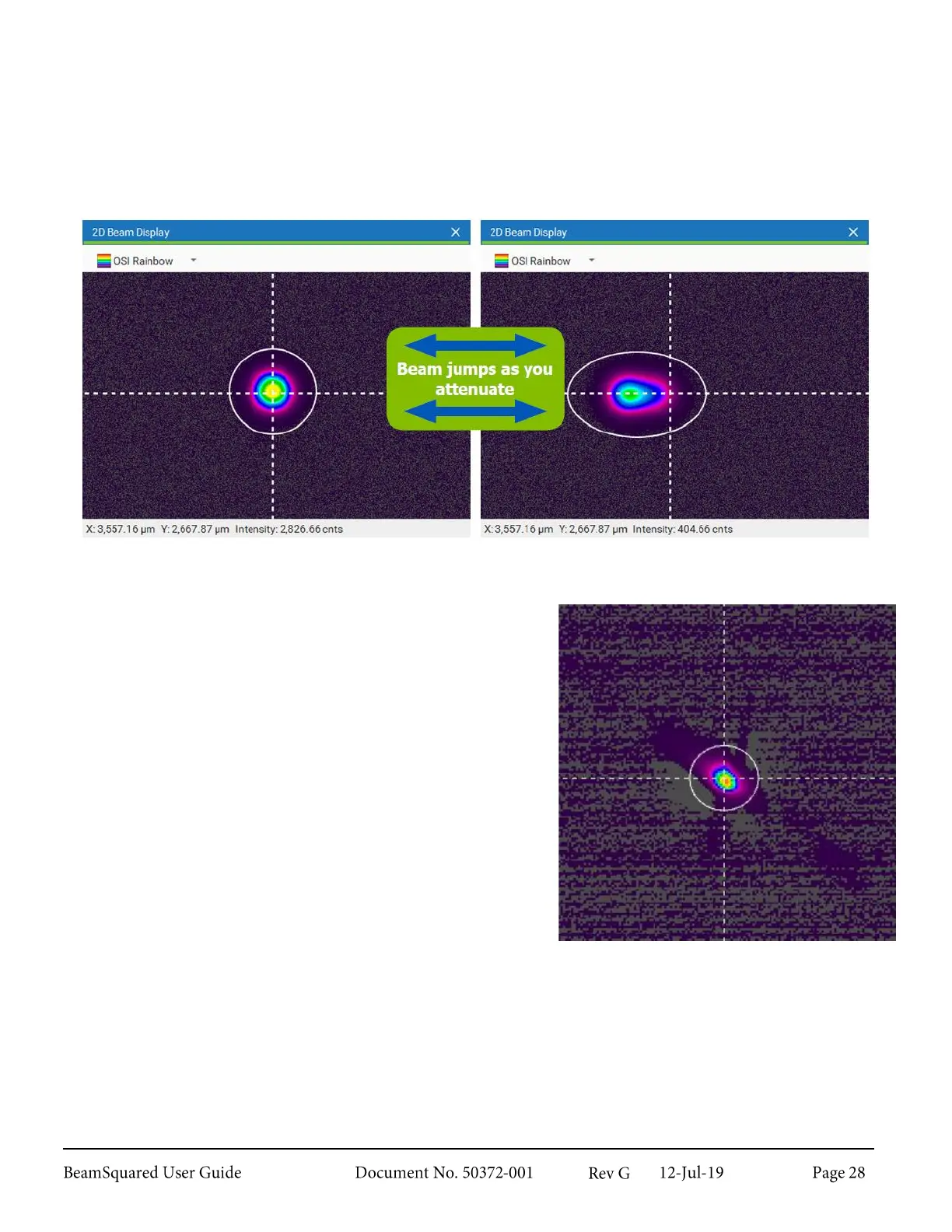
To identify a misalignment to a ghost beam, first follow the 2.5.3 Precision Beam Alignment instructions. Then
adjust the attenuation level. If the laser spot on the sensor appears to smear and jump out of view when the
internal attenuator is translating, then the system is aligned to either the secondary or tertiary reflections
shown in the diagram above.
To correct for a misalignment to a ghost beam, adjust the alignment of the steering mirrors until you find the
primary spot; then follow the 2.5.3 Precision Beam Alignment instructions to finalize beam alignment.
Beam Axial Alignment 2.5.4
In the image to the right the asymmetrical beam is poorly
aligned with the camera axes. Unless the beam is circular, axial
alignment is critical to obtain accurate results. ISO states that
when the ratio of the beam widths exceeds 0.87 the beam can
be considered circular.
For the beam shown, the profile is tilted approximately 45
degrees from the axes of the window. The calculations assume
a nearly circular beam even though it is elliptical.
If the camera axes coincide with the natural axes of the beam,
results calculated in rectangular coordinates have the largest
range of variation and contain the largest amount of
information about the beam.
Rotate the camera to bring the natural axes of the beam into
alignment. The intensity profile should inhabit an approximate
two-fold symmetry about the X and Y axes.