4.
Remove the Gunsight alignment tool
from the input port.
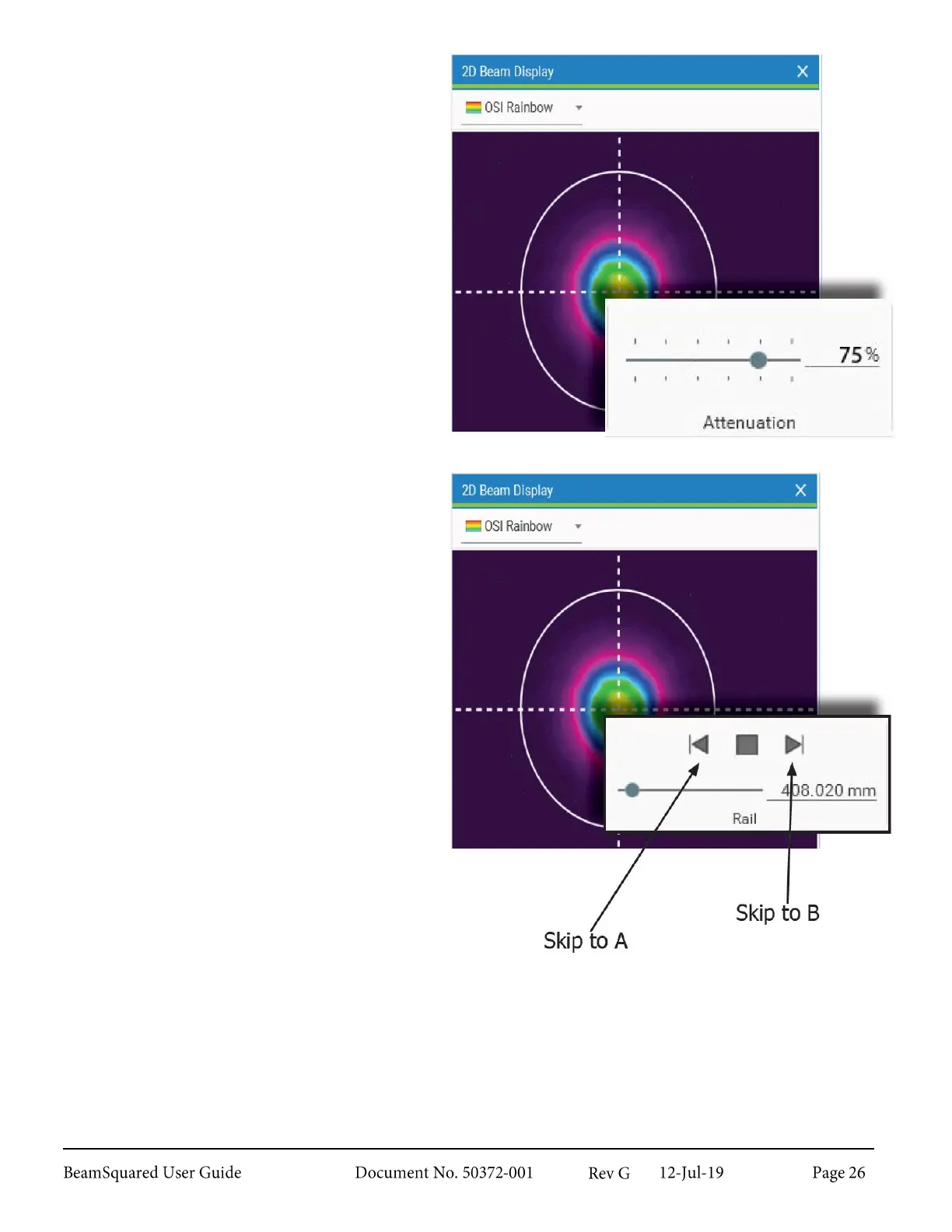
5.
Watch the laser beam in the 2D
Beam Display window. Adjust the
internal ND filters to 75% in the
Table ribbon bar. It is beneficial to
have excessive external attenuation in
place at this time to protect the
camera.
6.
Translate the table until the
approximate minimum beam diameter
is found. This is usually near the focal
length of the lens, but not always.
Gradually remove external attenuation
until the beam intensity is at
approximately 75% of camera
saturation.
7.
Use the translation controls on the
Rail panel under the Table ribbon bar
to change the Z location of the
camera.
8.
Watch the motion of the beam as the
table moves between rail positions “A”
and “B.” The beam image should stay
fairly centered in the camera array
without wandering significantly.
Precision Beam Alignment 2.5.3
If the beam does not remain centered as the table translates make additional small adjustments of the
steering mirrors. This is an iterative process where the mirror pair is adjusted in opposite directions and the
table is translated between “A” to “B” as necessary. In general, it is best to align one axis at a time to keep
the process simple.