Although the values for W
02
, Z
02
, and Θ
2
differ from those before the lens, the M
2
value remains the same. This
means the M
2
values remain constant as they propagate through optical devices, so long as those devices do
not introduce aberrations. This relationship allows the BeamSquared to analyze the laser beam after the
focusing lens and then calculate the beam’s actual propagation parameters.
The method used by BeamSquared to determine the size and location of the artificial waist involves taking a
series of beam width measurements on both sides of and passing through the artificial waist region. A curve fit
is applied to the measured data based on the hyperbolic propagation equation (Equation 4). The results of
this fit yield the artificial waist width (W
02
), the artificial waist location (Z
02
), and the artificial divergence angle
(Θ
2
). The solutions from the fit are then translated back to the real laser beam.
Operation Limitations 5.6
BeamSquared is subject to limitations not only due to the measurement technique employed, but also those
existing in the ISO case of propagation theory. Of the three basic types of aberrations that effect laser beams
(mode content, aperture induced diffraction, and optical defects), only mode content is suitable to the current
M
2
measurement methods. The latter two types of defects, depending on severity, yield varying degrees of
anomalous results using the present methods.
Because BeamSquared computes separate M
2
results for both the X and Y axes, the beam must exhibit either
radial symmetry or bi-fold symmetry about these axes. Radially symmetric beams will produce nearly identical
results for each axis. And conversely, non-radially symmetric lasers will produce differing results for each axis.
Beams that contain simple on-axis astigmatism are easily measured with BeamSquared. However, beams that
are generally astigmatic (or twisted) cannot be accurately measured. If the laser is unstable in mode or
wavelength during the measurement period, the measurement accuracy will be degraded.
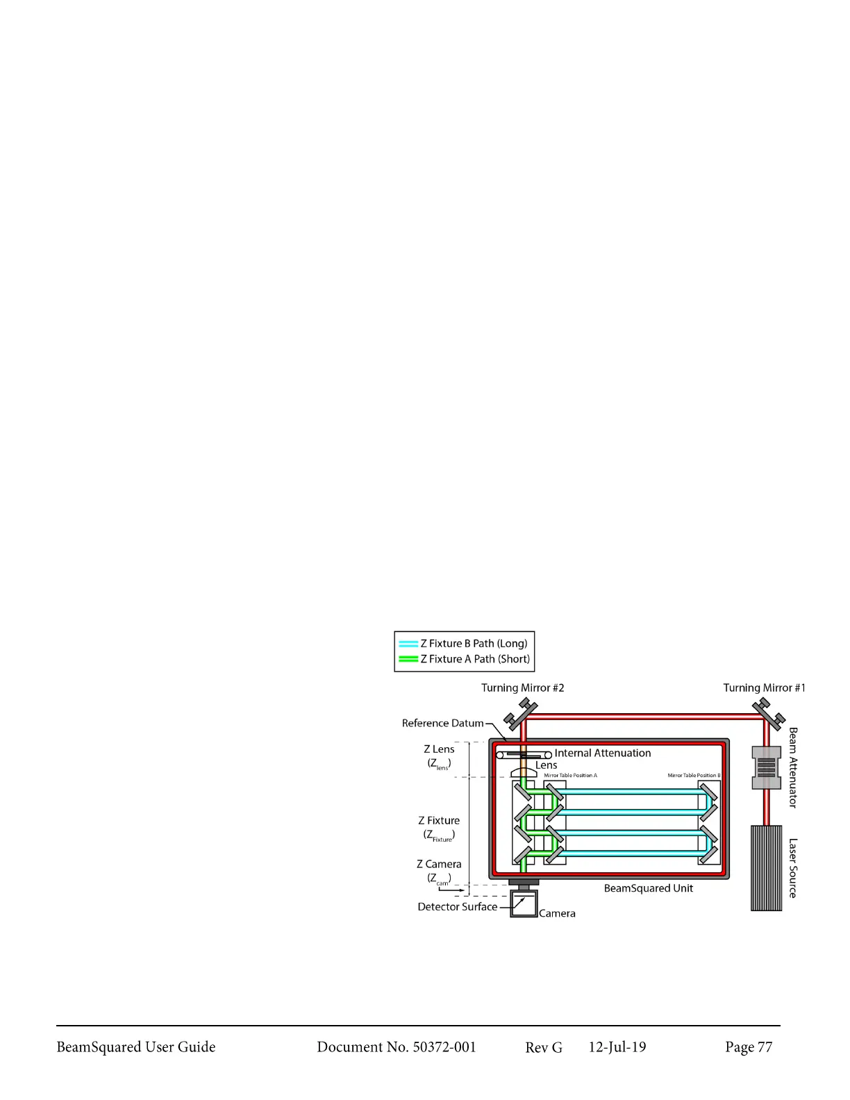
Electro-Mechanical Operation 5.7
Mirrors effectively translate a stationary camera along the focused beam’s optical path.
As the mirrors move from “A” to “B”, the camera
detects the changing laser beam profile. During
the collection process the internal attenuation
will automatically adjust for changes in the
apparent brightness of the image.
Whenever the background energy of the camera
drifts, the software automatically recalibrates the
baseline.