crossing the Z match planes, the waist locations, z4
and z5, are calculated with higher accuracy. This
occurs due to the curvature of the calculated fit
between z2 and z3. When placed in a region of
greater curvature (such as occurs inside the Rayleigh
lengths), the linear interpolation becomes less precise
with respect to the real curve.
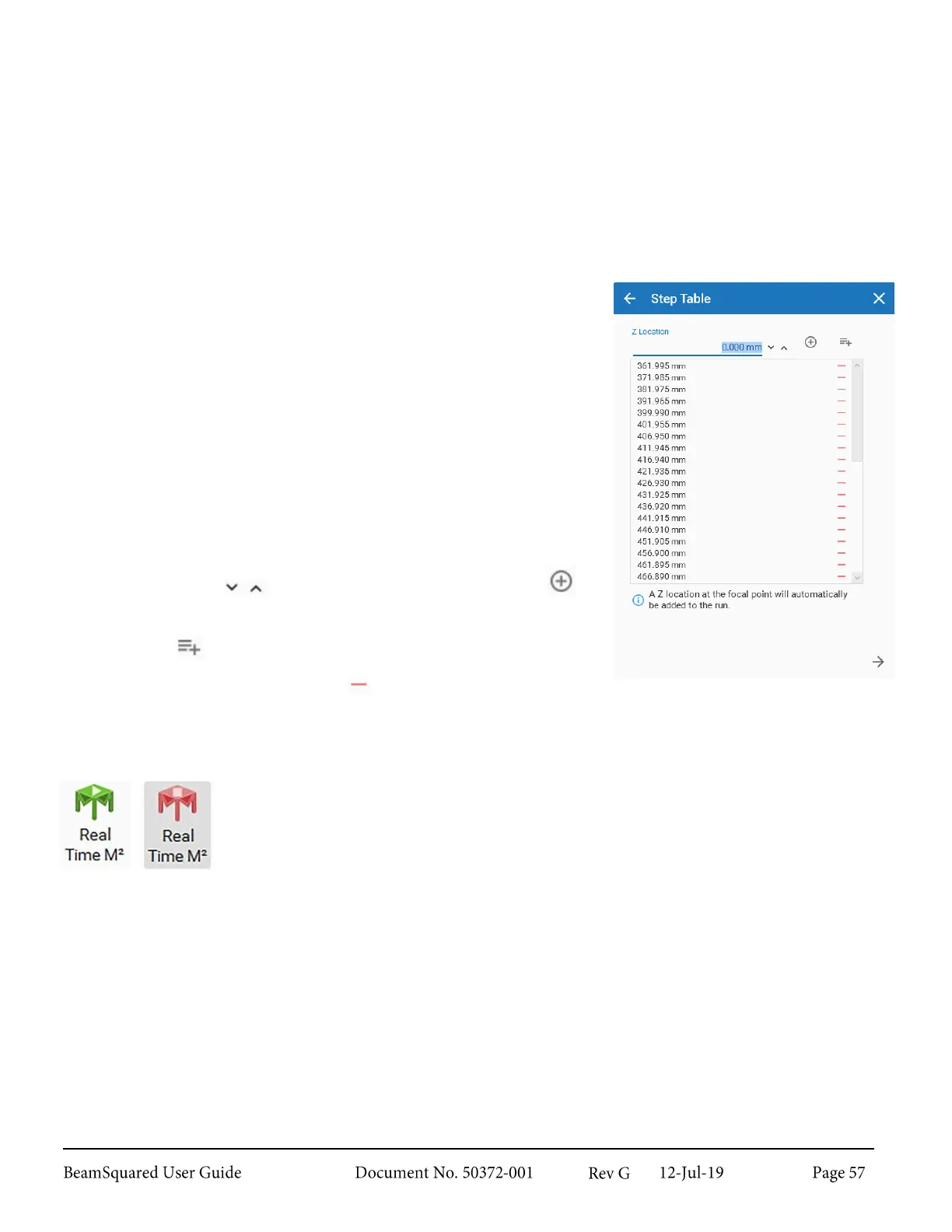
Step Table 4.1.4
The Step Table allows each data point to be entered in manually
which permits every beam propagation measurement to be taken at
the same locations in the Z axis. Include as many or as few data points
or Z locations in the Step Table.
To minimize measurement time and optimize the measurement
accuracy it is recommended the same scrutiny is used when selecting
the Z locations for the Step Table as for any other method.
Start and Stop locations as well as the number and location of
additional steps must follow the same criteria as mentioned for the
other measurement methods.
Data points can be typed into the Z Location entry field or adjusted by
increments of 1 with . Select Enter or Add Z Location to
add a value to the list.
Fill From Run fills the table with the Z locations from the last run.
Select the Remove Z Location icon on any data point that is not
desired to remove it from the list.
Real Time M
2
Mode 4.1.5
The Real Time M
2
mode provides continual, real-time monitoring of a laser beam. It
may be used to monitor a laser while the laser cavity is under adjustment, providing a
fast M
2
estimate to the technician during the tuning process. It may also be used to
monitor laser output under normal operating conditions or may be used to monitor
laser stability over any time span.
This technique has reduced accuracy and is not ISO compliant. It should not be used as
a substitute for standard M
2
measurements. After laser adjustments are complete,
another standard M
2
measurement should be made in order to obtain actual results.
Real Time M
2
only becomes available after a successful M
2
data collection run has
completed. When enabled, the translation system places the camera at the focal length
of the lens, sets the internal attenuation, and performs an Ultracal baseline calibration.
It then computes, in real-time, the current divergence value and the estimated M
2
along both the X and Y axes. The new M
2
value is estimated based on the change in
beam divergence and the results from the previous run.