Attenuation and Distortions 5.4.4
Ideally, no optical devices would be placed in the beam path since these can introduce distortions into the
beam. However, most applications require attenuation. It is essential to reduce the total input beam power
before the beam enters the camera to avoid damaging the detector.
Damage to the camera may occur if input power exceeds the limits listed in the camera
specifications (see Appendix C). Notice that the highest power density levels occur at the
beam focus. The camera sensors are very costly to replace and are not covered for
damage under Ophir-Spiricon’s standard warranty.
M
2
Theory of Operation 5.5
BeamSquared measures beam parameters by combining an aberration free lens, a detector translation system,
and the requirements described in the ISO procedure.
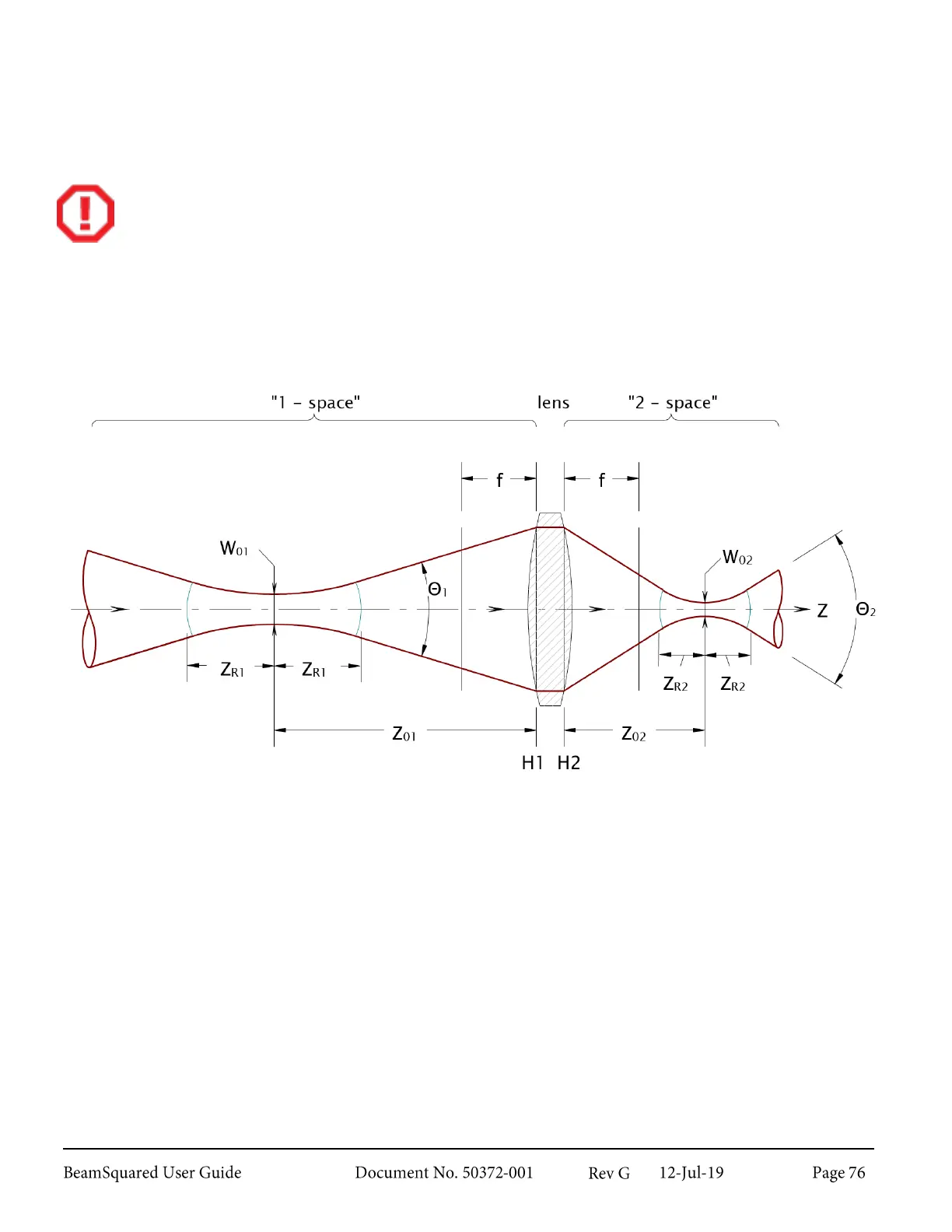
The beam passes through the lens to create an artificial waist, or focus spot. The propagation of the laser
beam through a focus has a direct relationship to how the real unfocused beam propagates in space and is
described by the same equation used in Equation 1. A 2 subscript is used to denote a lens origin and the
distance, z, is now measured from the lens.
Equation 4 – Hyperbolic Propagation
Where:
The beam width at the artificial waist (the minimum focused spot size)
The artificial waist location (measured from the lens)
The artificial far field divergence angle