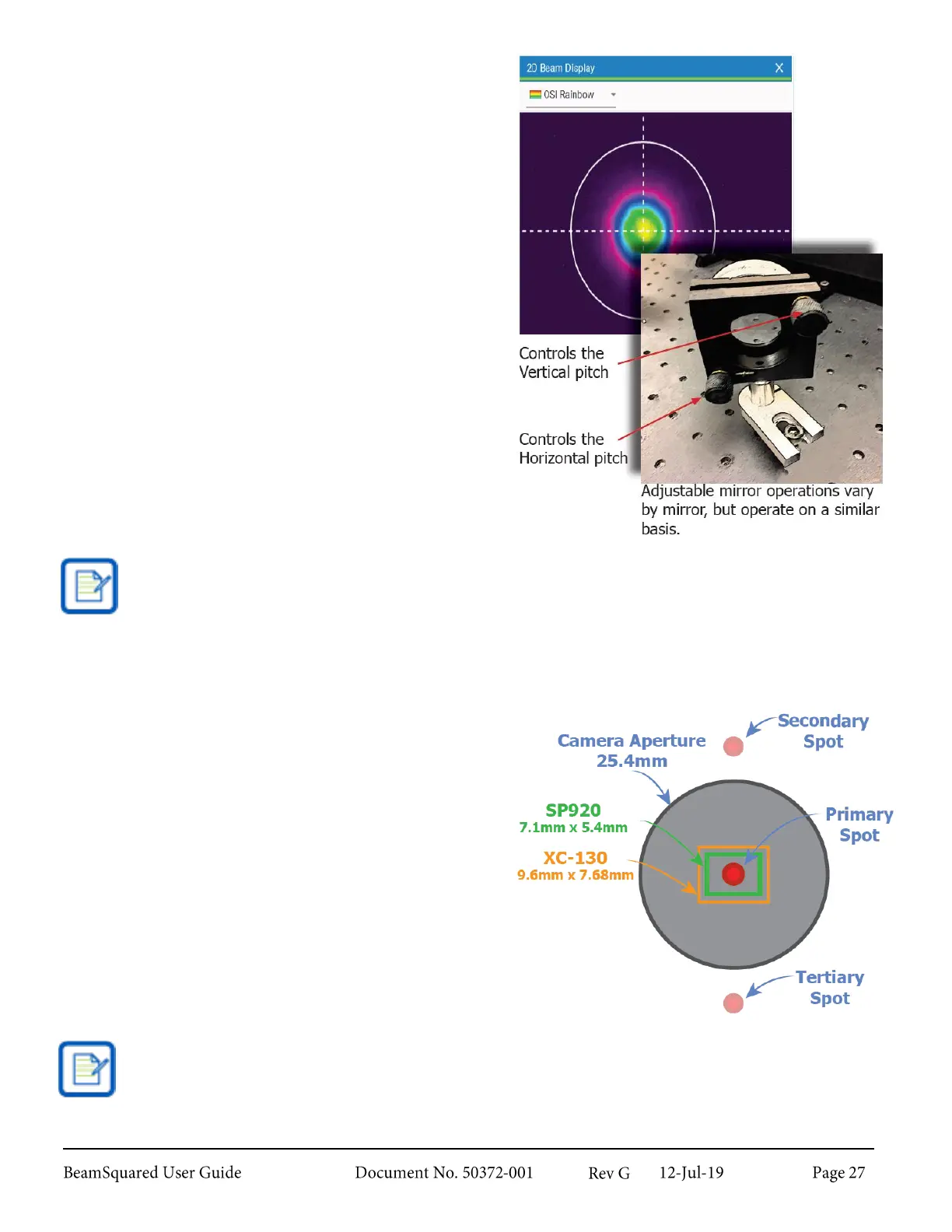
1.
Move rail to position “A.”
2.
Enable Live Playback on the Run ribbon.
3.
Move rail to position “B.” During this step, watch
the direction of beam movement on the 2D
Beam Display.
4.
Move rail to position “A.”
5.
Adjust Mirror #1 to direct the beam in the same
direction observed in Step 3.
6.
Using Mirror #2, adjust the beam back to the
center of the CCD array.
7.
Repeat steps 1-6 as necessary until beam is
centered on the CCD array through the entire
propagation path.
8.
Once a stable alignment is obtained, disable Live
Playback on the Run ribbon to turn off the live
video alignment mode.
Making adjustments greater than ½ to 2 times the width of the CCD array makes it easy to lose
track of the beam.
Ghost Beams 2.5.3.1
The optical path design of the BeamSquared system
creates some natural reflections of the input laser. While
most ancillary reflections are orders of magnitude below
detection levels, the secondary and tertiary reflections of
the input laser land near, but outside of the camera
aperture and can be detected and aligned to if the user is
unaware of them. These spots appear much dimmer, and
issues may arise in the propagation measurements if you
align to one of these "ghost beams."
The secondary and tertiary points in this depiction are shown along the Y axis of the camera. This
only applies when the BeamSquared unit is mounted horizontally and the camera us upright. If the
BeamSquared unit is mounted vertically and the camera is upright, the secondary and tertiary points
are then found along the cameras X axis.