ELE-3
2-3. Tension Sensor Voltage
Adjustment (1)
BOARD SERVO (F1)
TP TP201
ADJ. VR1 (OFFSET) on the Mech. I/F board
TAPE -----
INPUT -----
MODE EJECT
M. EQ VFK1191A (Dial Torque Gauge)
VFK1152 (Dial Torque Gauge Adaptor)
SPEC. 2.5V ± 0.05V
1. Connect the Digital voltmeter to TP201.
2. Adjust the VR1 on the Mech. I/F board so that the
DC voltage is in the specification.
2-4. Tension Sensor Voltage
Adjustment (2)
BOARD SERVO (F1)
TP TP201
ADJ. Sensor Position, VR2 (GAIN)
TAPE -----
INPUT -----
MODE EJECT
M. EQ Digital voltmeter,
VFK1208
(Neutral Position Tool, Black with hole)
VFK1156 (PLAY Position Tool, Black)
SPEC. Neutral position : 2.5V ± 0.1V
PLAY position : 3.8V ± 0.05V
NOTE:
Do not use magnetized tweezers and
screwdriver.
Do not touch the magnetize screwdriver to S-Reel
FG magnet portion, while adjusting the lever (D)
portion.
<Preparation>
1. Unscrew the 2 screws and remove the Carriage
Support Panel on the Front Loading Unit.
2. Disconnect the connector P3 on the Carriage
Board of the Front Loading Unit.
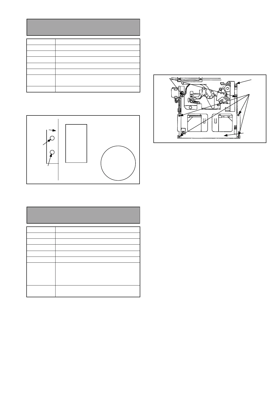
3. Unscrew the 6 screws and remove the Top Plate
on the Front Loading Unit as shown in figure
below.
4. Connect the Flexible cable to P3 on the Carriage
Board of Front Loading Unit.
<Adjustment Procedure>
1. Open the SERVICE MENU.
2. Select the A00: SERVO ADJUST and press the
“SET” button to open the SERVO ADJUST
MENU.
3. Select the A09 TENSION.
4. Install the VFK1208 (black with hole) as shown in
figure.
5. Connect the Digital voltmeter to TP201.
6. Lean the “JOY STICK” rightward so that the
mechanism shifts to the Loading mode.
7. Confirm the DC voltage at TP201 is 2.5V ± 0.1V
(Neutral position). If it is not, adjust the sensor
position as follows.
Loosen the screw (A) and move the lever (D) with
tweezers. After adjusting, rotate JOG dial counter
clockwise pushing Search button to set the
unloading position.
8. Remove the VFK1208 (black with hole), and
install the VFK1156 (Black) as same way as
VFK1208.
9. Lean the “JOY STICK” rightward so that the
mechanism shifts to the Loading mode.
10. Adjust the VR2 (GAIN) on the Mech. I/F board so
that the DC voltage at TP201 is 3.8V ± 0.05V
(PLAY position).
11. Close the Menu.
S Brake
Solenoid
Mechanical
Chassis
S Reel
VR2
GAIN
VR1
OFFSET
Mech. I/F
Board
P3
SCREW
SCREW
TOP PLATE