ELE-11
< Note >
After replacing the cylinder unit, perform the
paragraphs 4-1, 4-2, and 4-3. “RF Level Adjustments”
before performing LISTA adjustment.
5-1. RF Level Adjustment (50M)
BOARD RF/CUE
TP
See Table Below
ADJ.
Service Menu
INPUT
----
MODE
STILL
TAPE
VFM3580KM or KL (Color Bar) [NTSC]
VFM3680KM or KL (Color Bar) [PAL]
M. EQ
Oscilloscope
SPEC.
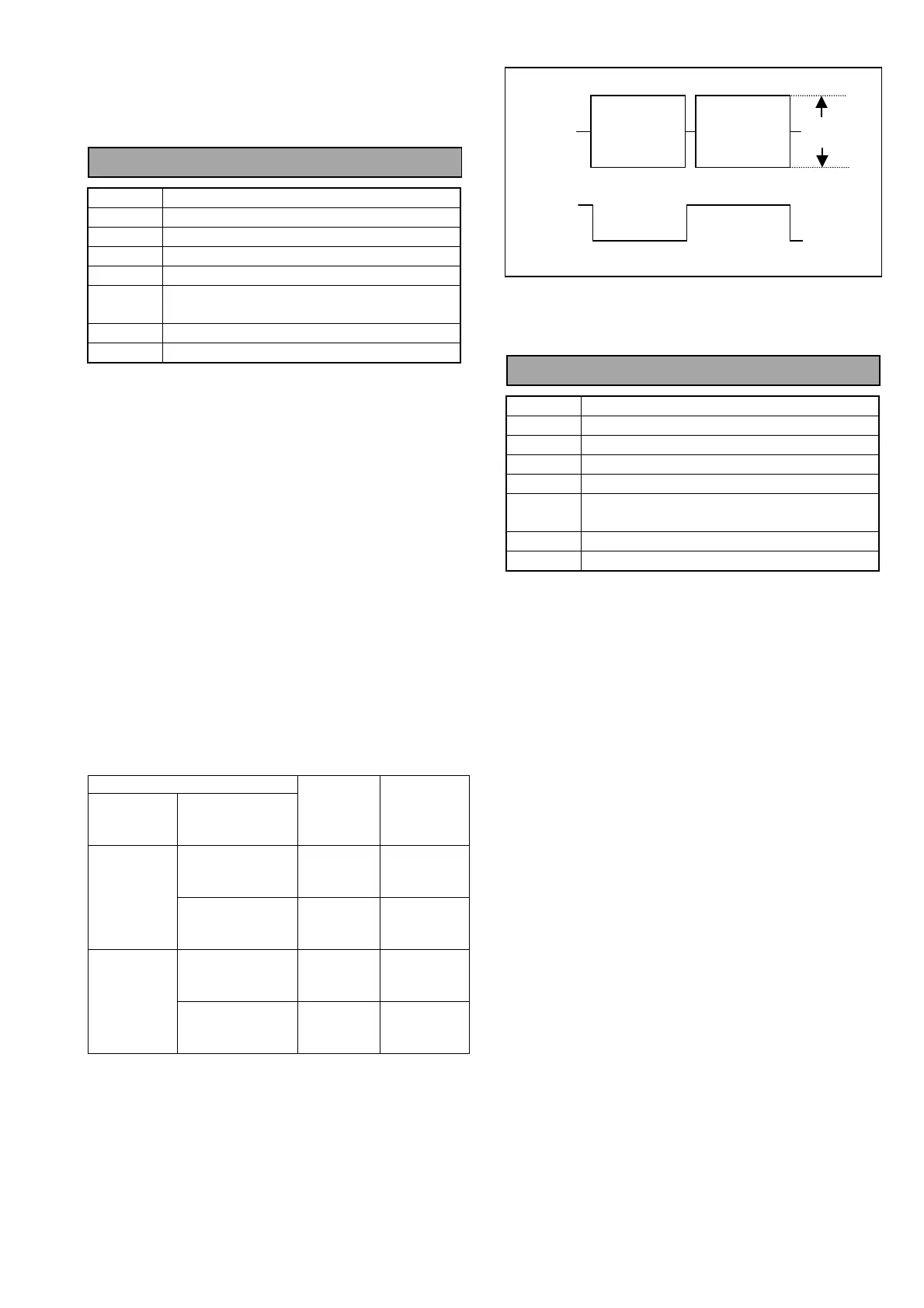
A Max = 600mVp-p ± 100mV
<Service Menu Setting>
B00:RF ADJUST → P00:DVCPRO 50M ADJUST
1. Open the service menu and select the above and
then select “P-2: PB ADJUST” on the RF Adjust
sub screen 2.
2. Select “P03: ATF MAG L1” on the item select
screen.
3. Connect the oscilloscope to Measuring Point
(MP) and Trigger Point (TG) as shown in the table
below.
4. Play back the 25M alignment tape in the STILL
mode.
5. Adjust the EVR so that the envelope maximum
level is in the specification.
6. To save the EVR data, select “P-4 DEFAULT” and
press the “JOY STICK”, then select “SAVE”,
press the “JOY STICK” again.
7. Perform the same steps for the PB L2, PB R1/R2,
RP L1/L2 and RP R1/R2 heads.
P00:DVCPRO 50M ADJUST
(RF ADJUST SUB SCREEN 1)
SERVICE MENU
RF ADJ.
SUB
SCREEN 2
ITEM SELECT
SCREEN
TEST
POINT
(RF/QUE)
TRIGGER
POINT
(SERVO)
P03:ATF MAG L1
P04:ATF MAG L2
TP5301
EQ0
ATFLEV
TP232
(HSW PB L)
P-2:
PB ADJUST
P07:ATF MAG R1
P08:ATF MAG R2
TP5501
EQ1
ATFLEV
TP234
(HSW PB R)
P03:ATF MAG L1
P04:ATF MAG L2
TP5301
EQ0
ATFLEV
TP233
(HSW RP L)
P-3:
RP ADJUST
P07:ATF MAG R1
P08:ATF MAG R2
TP5501
EQ1
ATFLEV
TP235
(HSW RP R)
5-2. RF Level Adjustment (25M)
BOARD RF/ CUE
TP
See Table Below
ADJ.
Service Menu
INPUT
----
MODE
STILL
TAPE
VFM3580KM or KL (Color Bar) [NTSC]
VFM3680KM or KL (Color Bar) [PAL]
M. EQ
Oscilloscope
SPEC.
A Max = 600mVp-p ± 100mV
<Service Menu Setting>
B00:RF ADJUST → Q00:DVCPRO 25M ADJUST
1. Open the service menu and select the above and
then select “Q-2: PB ADJUST” on the RF Adjust
sub screen 2.
2. Select “Q03: ATF MAG L1” on the item select
screen.
3. Connect the oscilloscope to Measuring Point
(MP) and Trigger Point (TG) as shown in the table
below.
4. Play back the 25M alignment tape in the STILL
mode.
5. Adjust the EVR so that the envelope maximum
level is in the specification.
6. To save the EVR data, select “P-4 DEFAULT” and
press the “JOY STICK”, then select “SAVE”,
press the “JOY STICK” again.
7. Perform the same steps for the PB L2, PB R1/R2,
RP L1/L2 and RP R1/R2 heads.
“A” (MAX)
TP5301
OR,
TP5501
TP232,
TP234,
TP233
OR,
TP235