MECH-17
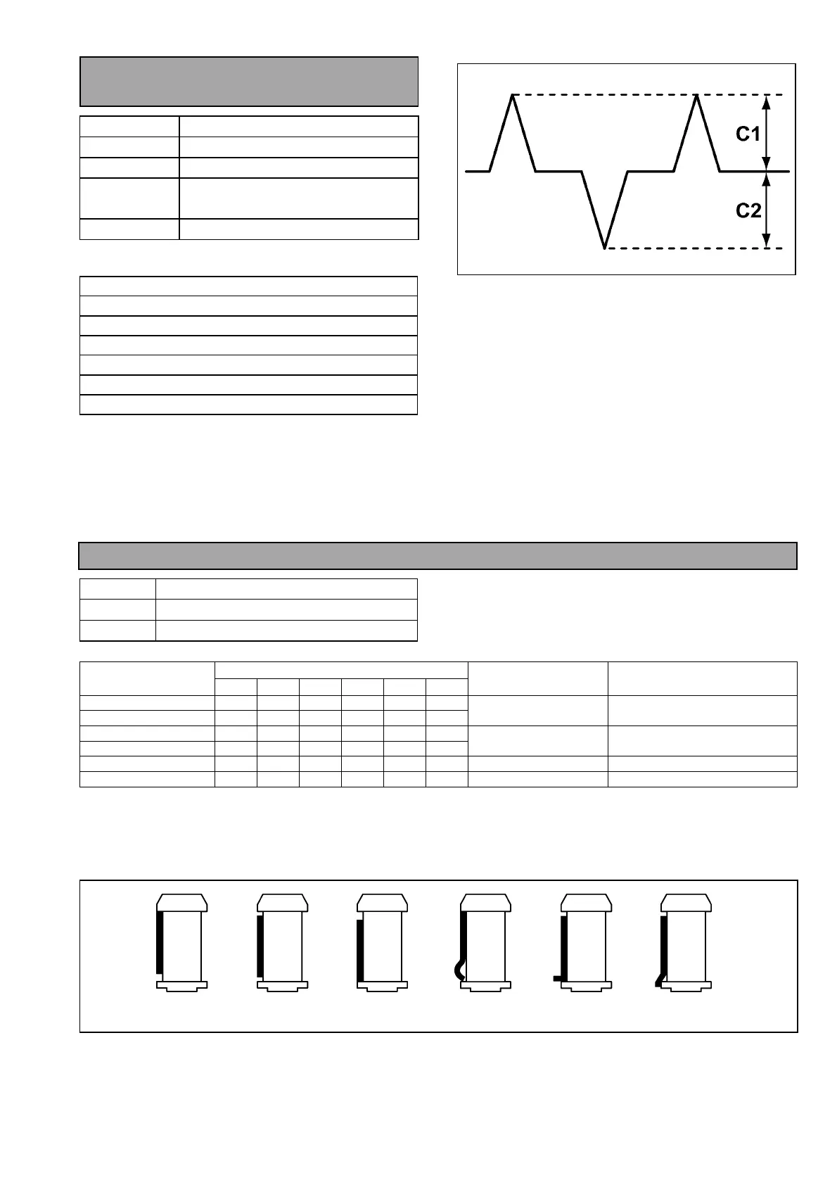
3-21. CTL Self Recording Level
Confirmation
TEST POINT
TP30 : SERVO
ADJ.
T4 post height
MODE
PLAY, REV×1, REV×0.2
TAPE
Blank Tape
M cassette 66 min
M.EQ
Oscilloscope
(Specification for confirmation)
CTL Out
ut Level : C1
C2
PLAY
C1, C2 ≥ 1.8 V
REV
SHTL x-1
C1, C2 ≥ 1.4 V
REV
SHTL x-0.2
C1, C2 ≥ 1.2 V
Figure 3-21-1
1. Confirm that the each screws are fixed on A/C
Head.
2. Place the Unit into DVCPRO 25M REC mode and
playback the recorded portion.
3. Confirm that the CTL level is within the
specification at PLAY and REV mode.
4. If CTL level is out of specification at PLAY mode,
confirm the height of A/C Head (refer to item “3-17.
A/C Head Height Confirmation”)
5. If CTL level is out of specification at REV mode,
confirm the height of T4 Post (refer to item “3-20.
REV Tape Path Confirmation and Adjustment”).
3-22. Play Tape Path Limit Confirmation
SPEC
Each post limit shown in figure below.
MODE
PLAY
TAPE
VFM3580KM/L or Blank Tape
Tape limit (refer to figure)
Post Name
A B C D E F
Adjustment
Point
Adjustment
Item
S5 post NG OK OK NG NG NG
S4 (Tension) post NG NG OK NG NG NG
S4, S5 post Post Height Pre-Adjustment
S1 post OK NG NG NG NG NG
T1 post OK NG NG NG NG NG
S1, T1 post ENV Waveform Adjustment
T3 post NG NG OK NG NG NG A/C Head tilt screw A/C Head Tilt Adjustment
T4 post OK OK OK NG NG NG T4 post Post Height Pre-Adjustment
Table 3-22-1
1. Place the unit into PLAY mode and confirm that the each post limits is within the specification.
2. If it is out of specification, adjust the post height by following the each adjustment procedure (Refer to above
table).
Figure 3-22-1
A : UPPER B : FREE C : LOWER D : CURL E : BEND F : DROP