ELE-9
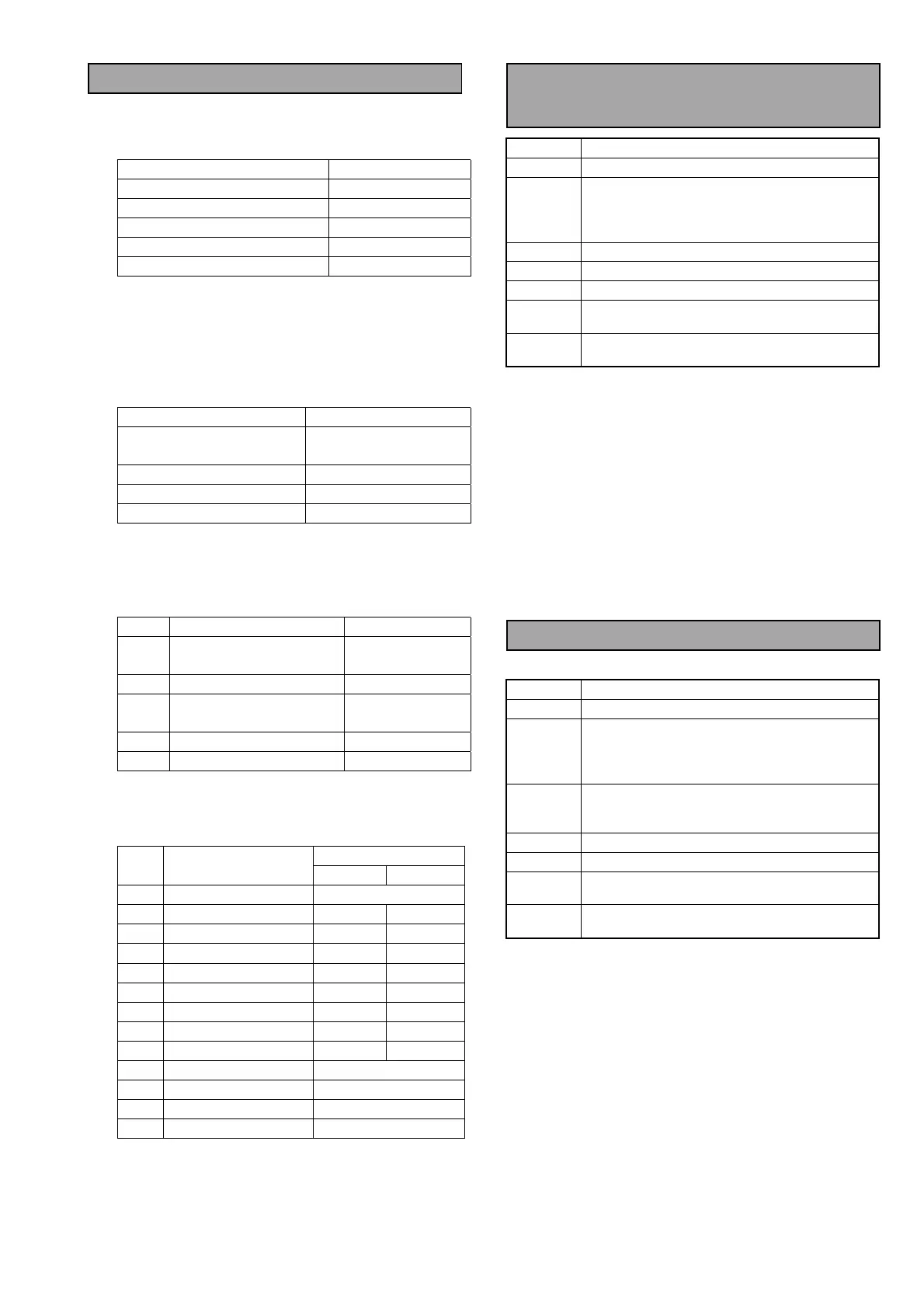
4-4. Audio Initial Setting
<Switches on the Front Panel>
Set the Switch and Control on the Front Panel as
shown below.
Switch & Control Setting
REC/PB VR (CH1,2,3,4) Center Click Point
REC/UNITY/PB UNITY
AUDIO IN ANALOG
REMOTE/LOCAL LOCAL
MONITOR L (CH1), R (CH2)
<Switches on the AVIO Board>
SW100 : High
SW101 : High
<Audio Analyzer Setting>
Set the Audio Analyzer as shown below.
Item Setting
GENERATOR OUTPUT
50Ω
(A&B, BAL, FLOAT)
ANALYZER CHA INPUT
100Ω
ANALYZER CHB INPUT
100Ω
UNIT SETTING
dBu
<Service Menu Setting>
1. Open the USER Menu.
2. Press the “EJECT” + “STOP” + “MENU” buttons
together so that the SERVICE MENU appears.
No.
Item
Setting
G01 REF. LEVEL1
P : FS20
E/MC : FS18
G02 REF. LEVEL2
0dB
G03 REF.LV INI
P/E : 0dB
MC : 4dB
G05 MIC IN LV
DIS
< Setup Menu Setting for Audio >
Setting
No. Item
P/E MC
700 AUDIO IN SE L ANA
701 CH1 IN LV 0dB +4dB
702 CH2 IN LV 0dB +4dB
703 CH3 IN LV 0dB +4dB
704 CH4 IN LV 0dB +4dB
706 CH1 OUT LV 0dB +4dB
707 CH2 OUT LV 0dB +4dB
708 CH3 OUT LV 0dB +4dB
709 CH4 OUT LV 0dB +4dB
722 REC CH! CH1
723 REC CH2 CH2
724 REC CH3 CH3
725 REC CH4 CH4
4-5. Audio Output Level
Adjustment
BOARD
AVIO (F4)
TP
AUDIO OUT (CH1-CH4)
ADJ.
VR4500 [CH1 OUT LV]
VR4501 [CH2 OUT LV]
VR4600 [CH3 OUT LV]
VR4601 [CH4 OUT LV]
INPUT
INT SG 0)
MODE
EE
TAPE
---
M. EQ
Monitor TV, Oscilloscope,
Audio Analyzer
SPEC.
AJ-SD93P/E: 0 dBu
± 0.1dB
AJ-SD93MC : +4 dBu ± 0.1 dB
1. Set the Switches on the Front Panel as shown
below.
AUDIO INPUT SELECT SW : SG
REC/UNITY/PB SW : UNITY
2. Adjust VR4500, VR4501, VR4600 and VR4601
so that the Audio Output Level at CH1-CH4 is in
the specification.
3. Make sure that the Audio Output waveforms are
normal sine wave.
4-6. Audio Input Level Adjustment
BOARD
AVIO (F4)
TP
AUDIO OUT (CH1-CH4)
ADJ.
VR4200 [CH1 IN LV]
VR4201 [CH2 IN LV]
VR4202 [CH3 IN LV]
VR4203 [CH4 IN LV]
INPUT
AUDIO IN (CH1-CH4)
Sine Wave, 1 KHz,
AJ-SD93P/E : 0dBu, AJ-SD93MC: +4dBu
MODE
EE
TAPE
---
M. EQ
Monitor TV, Oscilloscope,
Audio Analyzer
SPEC.
AJ-SD93P/E : 0 dBu
± 0.1dB
AJ-SD93MC : +4 dBu ± 0.2 dB
1. Supply the following signal to the AUDIO INPUTS
(CH1-CH4).
1 KHz, 0dBu : AJ-SD93P/E
1 KHz, +4dBu : AJ-SD93MC
2. Adjust VR4200, VR4201, VR4202 and VR4203 so
that the audio level at the Audio Outputs
(CH1-CH4) is in the specification.