MECH-10
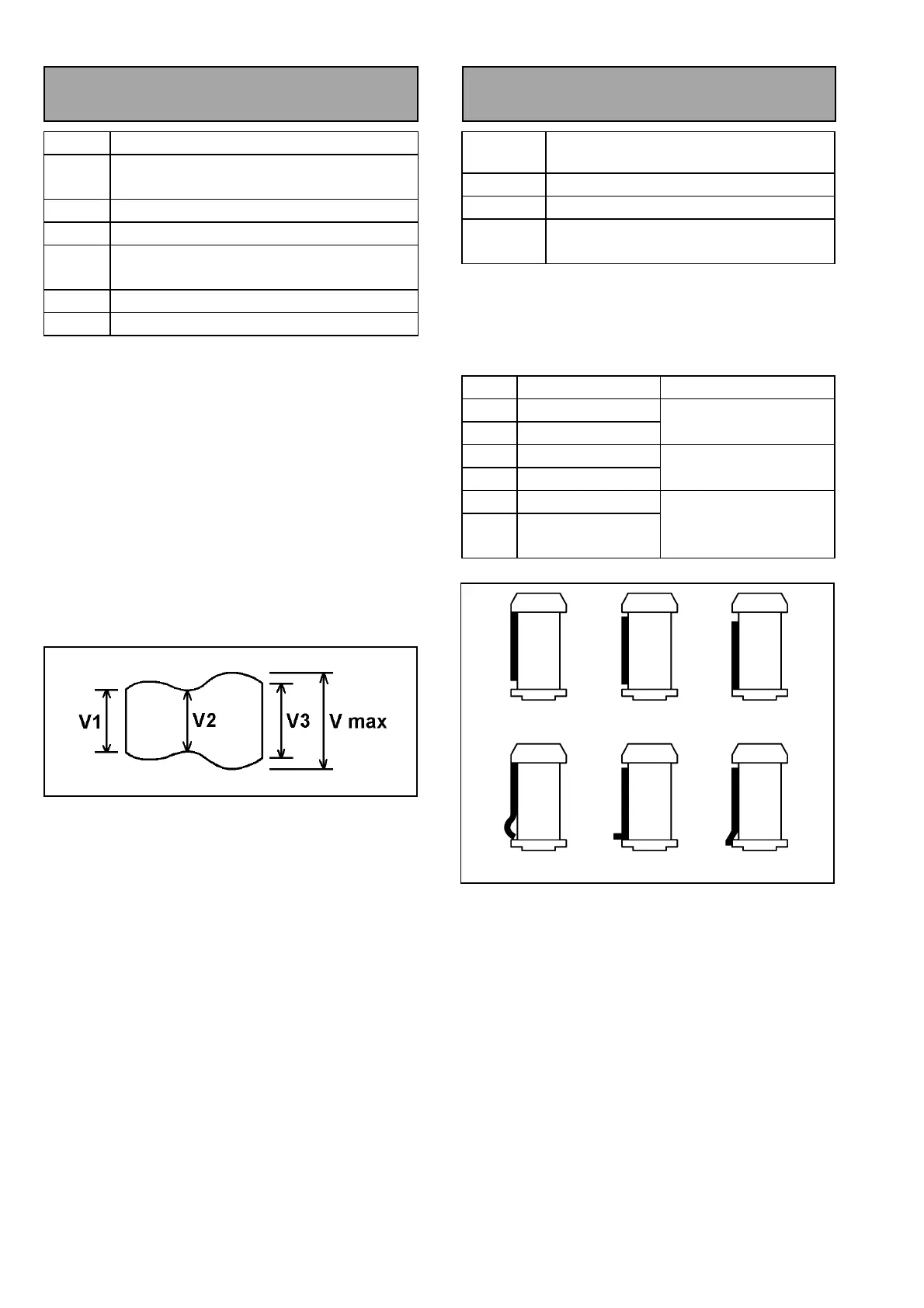
3-11. Envelope Waveform
Adjustment
SPEC
V1/Vmax, V2/Vmax, V3/Vmax ≥ 0.8
TEST
POINT
TP6302 (RF/ CUE)
ADJ.
S1, T1 Post Height
MODE
PLAY (ATF)
TAPE
NTSC : VFM3580KM or VFM3580KL
(PAL : VFM3680KM or VFM3680KL)
M.EQ
Oscilloscope
TOOL
VFK1149 or VFK1149B (Post Driver)
<Adjustment Procedure>
1. Playback the alignment tape with DVCPRO25
mode.
2. Adjust S1 and T1 post height so that the envelope
signal is within the specification.
3. To adjust the S1 or T1 posts, at first raise the post
height. Then the envelope at the entrance or exit
side becomes small. Then down the post hight
until envelope becomes flat.
4. As the order of adjustment, adjust T1 post to
make it flat at exit side of envelope first and then
adjust S1 post.
5. After finishing this adjustment, unload the tape
and load the tape again, then confirm the shape of
Envelope waveform does not change.
Figure 3-11-1
3-12. Post Limit Confirmation
(PLAY)
SPEC
Post limit is shown in the following table.
Curl should not appear on tape edge
MODE
PLAY
TAPE
Blank tape
TOOL
VFK1149 or VFK1149B (Post Driver)
VFK1151 (Nut Driver)
1. Confirm that the tape path limit meets the
specification in the following table. If not, adjust it.
2. Confirm that the tape path is not the condition of D,
E and F as shown in figure 3-12-1.
Post Limit Adjustment Method
S5 Lower limit or Free
S4 Lower Limit
Refer to Post Height
Pre-Adj.
S1 Upper Limit
T1 Upper Limit
Envelope waveform
Adj.
T3 Lower Limit
T4 Upper, Free or
Lower limit
Post Height Pre-Adj.
Figure 3-12-1
A: UPPER B: FREE C: LOWER
D: CURL E: BEND F: DROP